Ceres Air

Knowledge Base

How to upload the log

  1. Go to Remote Control
    image-1
  2. Select Log Management
    image (1)
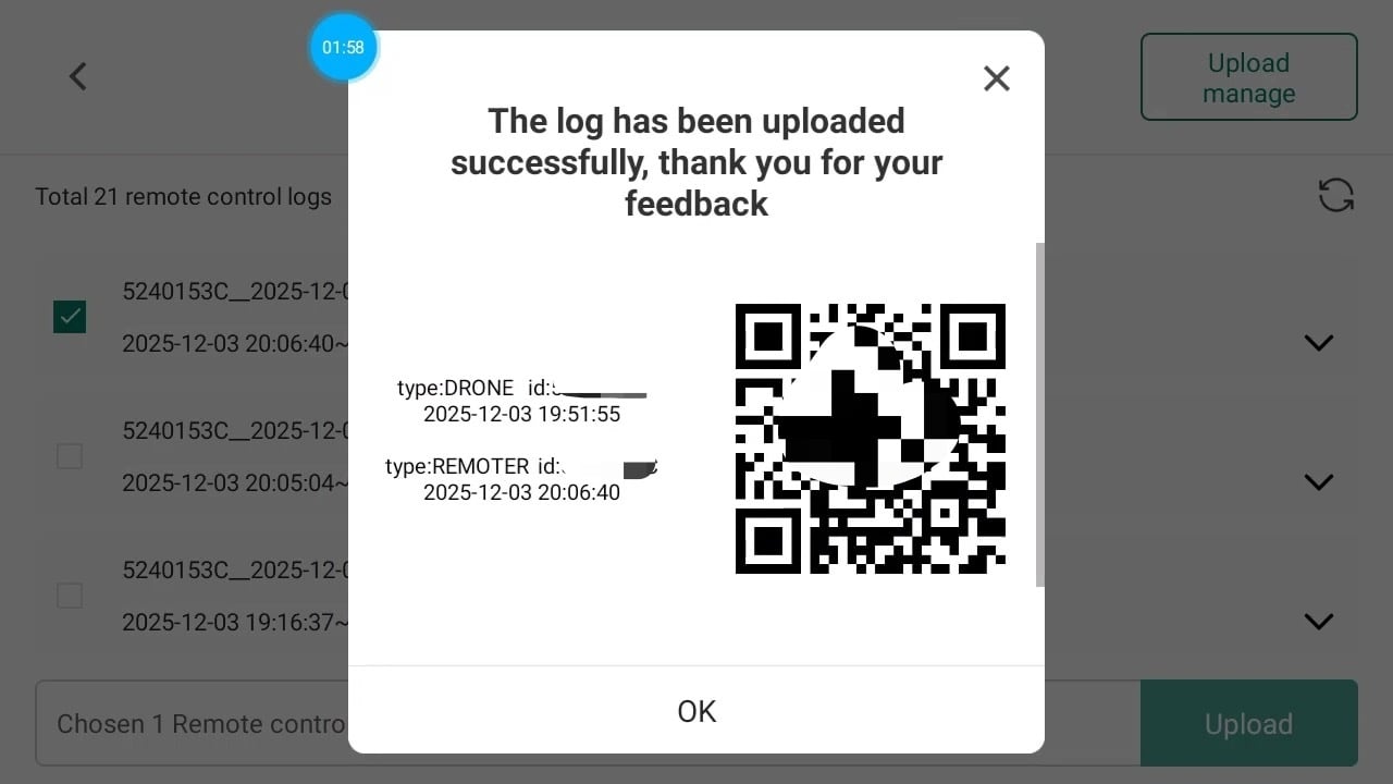
  3. Select logs to upload.
    image (2)
  4. Save the QR code and send it to support@ceresair.com
    IMG_0833


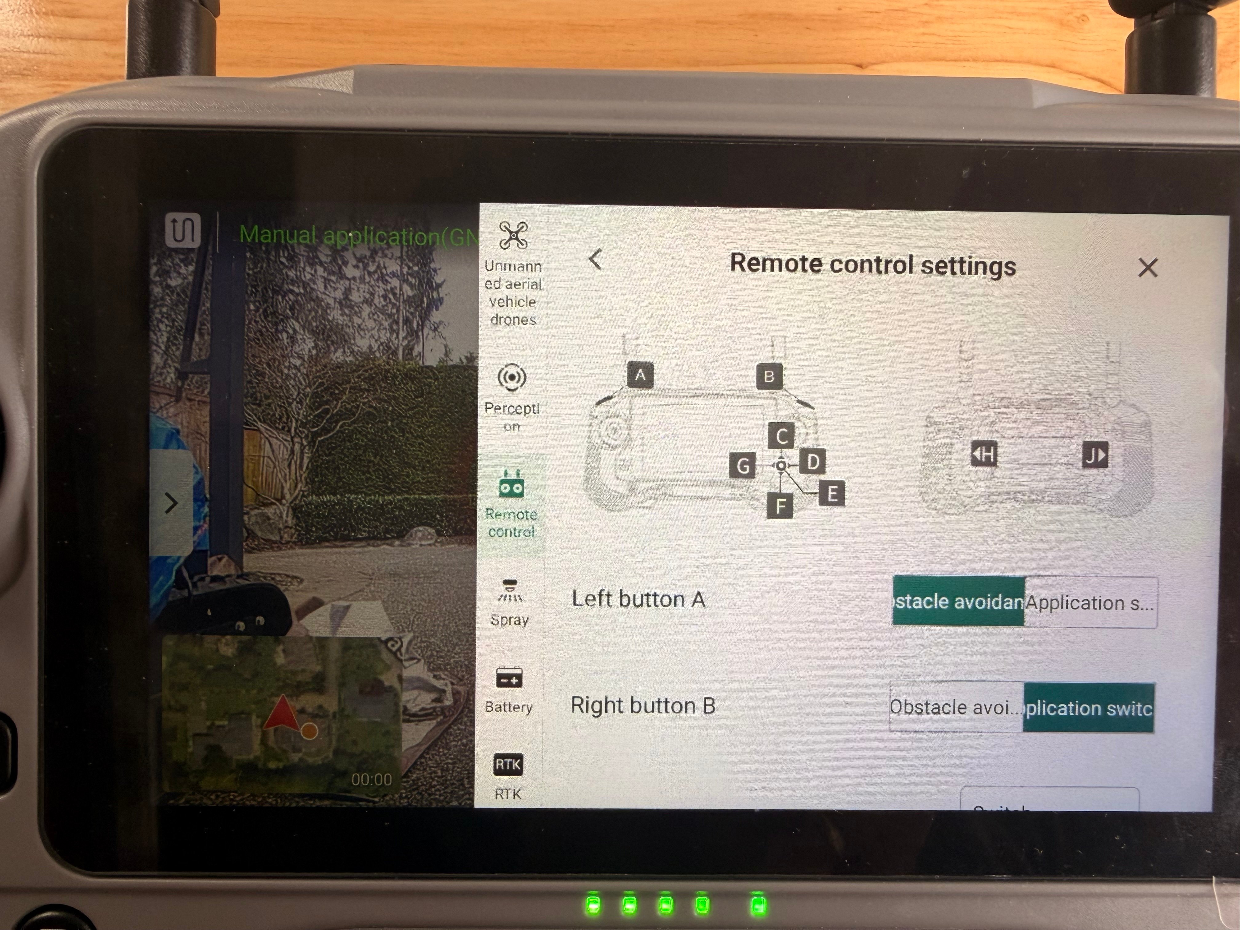
Setup Customize Key of Remote Control - Switch FPV Perspective

You can customize the key on the Remote Control for different functions.
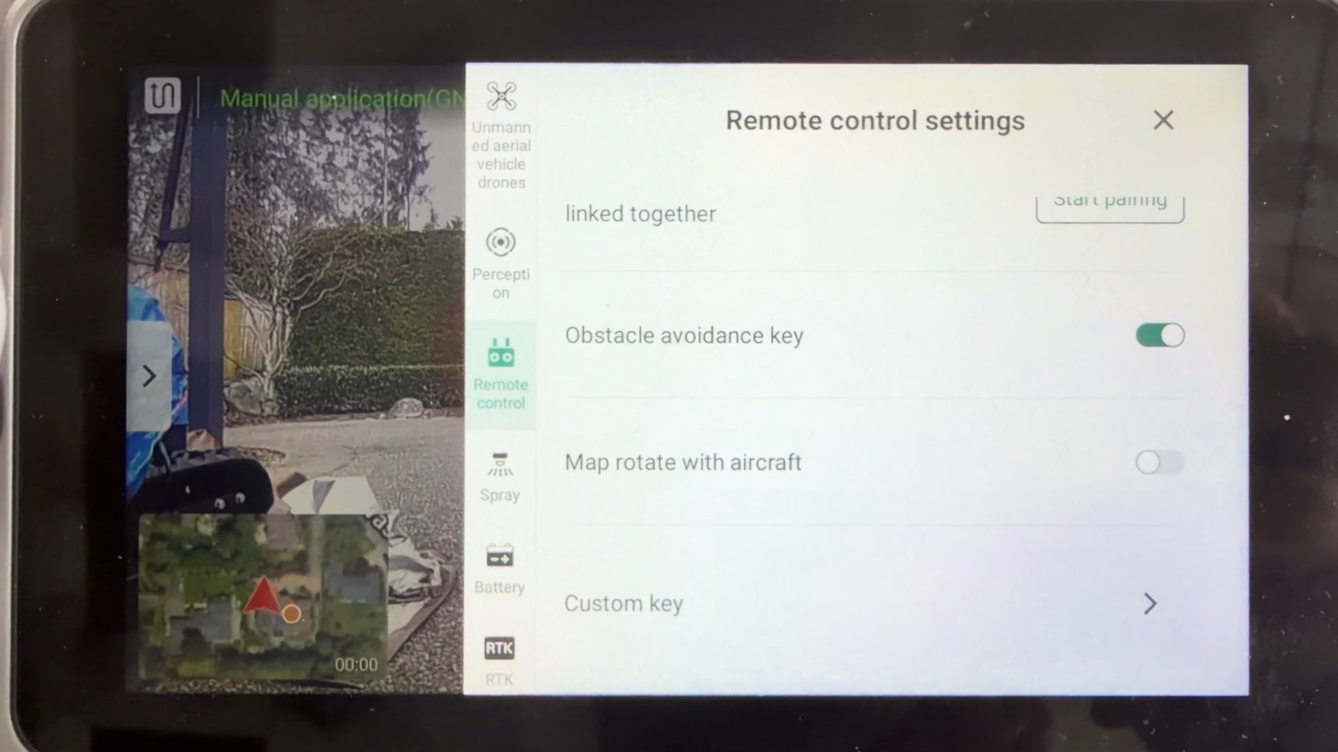
  1. Go to Remote Control setting → Custom Key
    63770BE6-B769-44FA-9732-AE0E35E1A7F5_1_206_a
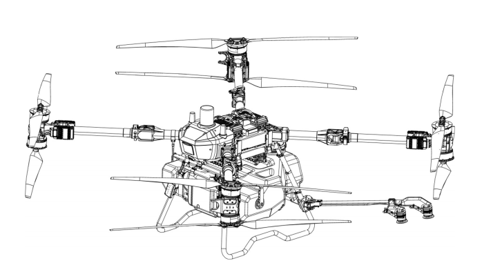
  2. Select the key you want to setup
    IMG_1256
  3. Select the function you want to setup
    IMG_1257

How to set up the Custom Key to Switch FPV Camera Perspective


Batch Importing KML Field Files to the Remote Controller V1.0

image-2


Version

Revision date

Revision department

Modify the description

Note:

V1.0

02/25/2026

Testing Services Department

First release


I. Import KML Files into the System

1. Log in to the system:

https://www.applicatorview.com

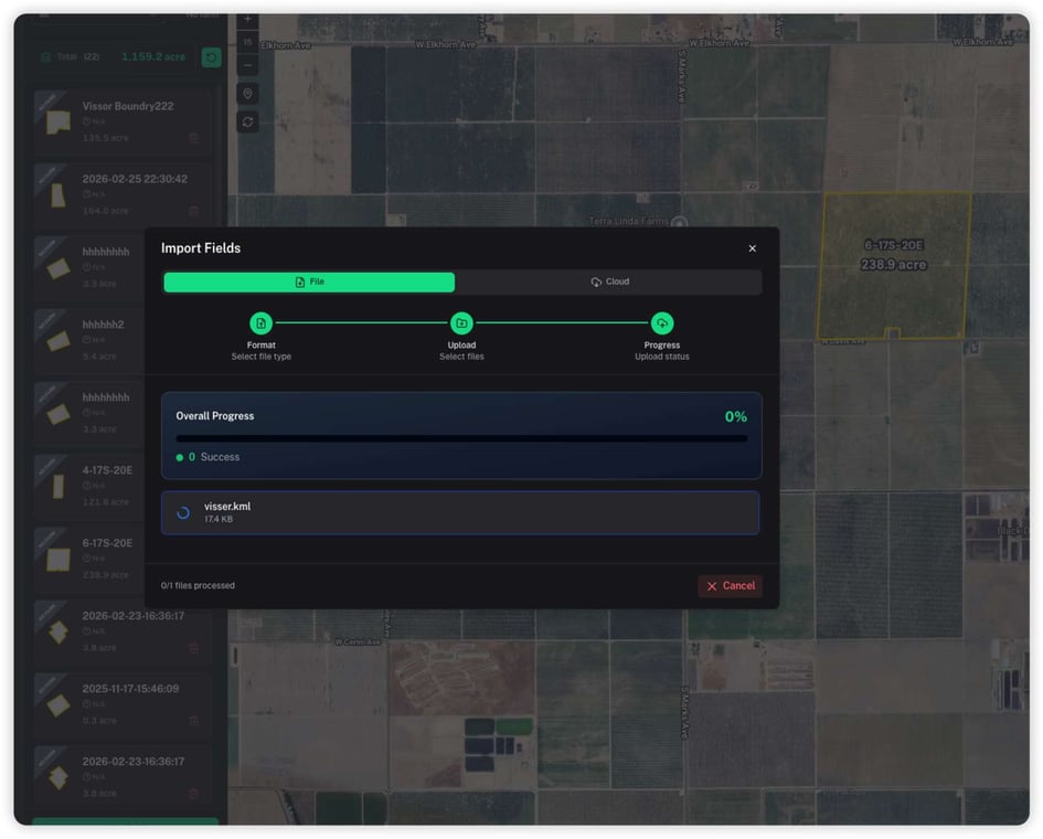
2. Go to Manage Fields and select Import Fields.

image (1)-1

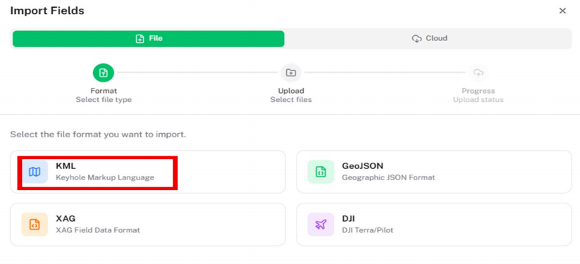
3. Choose KML as the file type.

image-3

image (1)-2

image (2)-1

4. Select the KML file(s) to upload (multiple files can be selected).

image (3)

5. Click Start Import.

image-4

image (1)-3

6. Check the import task status.

​Wait for the task to complete. You can refresh the page or the field list.

image (2)-2

7. Newly imported fields will be marked as “new.” Click on a field to view its details.

image (3)-1

image (4)

II. Push Fields to the Remote Controller

1. In the field details page, click the Push button.

image (5)

2. Monitor the task status to confirm completion.

image (6)

image (7)

2. Turn on the remote controller.

image (9)

3. Open Assignment Resources.

image (10)

4. Select Cloud, and locate the pushed field

image (11)

5. Select the field and click Download.

image (12)

image (13)

6. Switch to Local storage

image (14)

image (15)

7. Open the field to preview it.

The field can now be edited if needed.

image (16)

image (17)

image (18)


Remote Control App: Crash During Route Creation

Issue Description

Users may experience a critical failure when attempting to generate a flight route within the Remote Control app. The symptoms include:
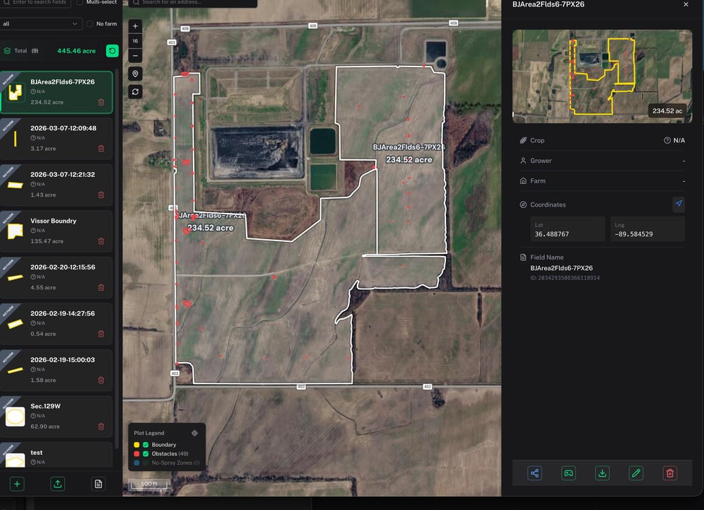
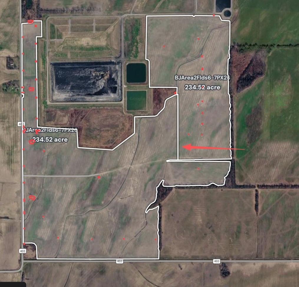
  1. A field boundary is successfully created and uploaded via the Applicator View.
  2. The field data is synced/pushed to the Remote Control.
  3. Upon attempting to create an operational route, the Remote Control app stops responding (hangs) or crashes.

img_v3_02vt_226b4ebf-5368-44ae-8e74-1018cefe95hu


Root Cause

img_v3_02vt_c884c4bf-a2d6-485e-82b9-53b2bae36ahu

The crash is caused by invalid polygon geometry within the field boundary. Specifically, the system cannot currently process boundaries that contain internal segments that "bisect" the field.

If a boundary line crosses through the interior of the shape—effectively splitting one field into two or more connected sub-sections—the routing engine fails. The Ceres Air Remote Control App does not yet support multi-field route generation within a single boundary container.

Resolution

To resolve this, you must ensure the field boundary is a single, continuous, and enclosed shape with no internal overlapping lines or intersecting boundaries.

Recommended Actions

Choose one of the following methods to fix the boundary:

  • Simplify the Boundary: Edit the field in the Applicator View to remove any internal lines, ensuring there is only one outer perimeter.
  • Segment the Fields: If the area truly requires two distinct sections, delete the "bisecting" boundary and save them as two separate, independent field files.

Best Practices: Field Boundary Creation

To ensure the Remote Control App generates flight routes efficiently and without errors, follow these geometric guidelines when mapping fields in the Applicator View.

1. Maintain Geometric Integrity

The routing engine requires a "Simple Polygon." To avoid app crashes:

  • No Self-Intersection: Ensure boundary lines never cross over themselves (forming a "figure-8").
  • No Internal Bisecting Lines: Avoid drawing lines that cut through the middle of the field. The boundary should only represent the outer perimeter.
  • Closed Loops Only: Always ensure the start and end points are snapped together to create a fully enclosed shape.

2. Managing Complex Fields

If a single physical location has distinct sections (e.g., divided by a road, a wide treeline, or a fence):

  • Create Multiple Fields: Instead of one complex boundary, save them as "Field A" and "Field B."
  • Avoid "Neck" Connections: Do not connect two large areas with a very thin "neck" of pixels, as this can confuse the pathfinding algorithm.

3. Handling Obstacles (No-Spray Zones)

When dealing with internal obstacles like silos, power poles, or ponds:

  • Use the "Hole" or "No-Spray" Tool: If the software supports it, define these as internal exclusions rather than trying to wrap the main boundary around them in a single continuous line.
  • Buffer Zones: Always leave a small margin of error (buffer) between the boundary and physical hazards to account for GPS variance.

4. Optimize Node Density

  • Limit Points: Avoid creating hundreds of individual points for a straight edge. Use the minimum number of nodes required to define the shape. High node density can slow down the sync process between the Applicator View and the Remote Control.


C31 Agricultural Drone Warranty Policy

C31 Agricultural Drone Warranty Policy

V1.0

imported-image (8)

1. Warranty Policy

  1. The entire product has a one-year warranty, and the main components have the following specific warranty periods:

Electronics

Components

Warranty period

Warranty period

FC (Flight Controller)

12 Months

24 Months

Radar (Rotation Radar , Rotation Radar)

12 Months

24 Months

Searchlight

12 Months

24 Months

FPV Camera

12 Months

24 Months

LiDAR

12 Months

24 Months

Front Interface Board

12 Months

24 Months

ESC

12 Months

24 Months

Smarter Battery

1500 cycles or 12 months (whichever comes first)

24 Months

Smarter Battery Charger

12 Months

24 Months

Remote Controller

12 Months

24 Months

Survey Tools

12 Months

24 Months

Base Station

12 Months

24 Months

Anatenna (RTK,WiFi)

12 Months

24 Months


1.2 Warranty Period for Other Components and Wearable Parts

Components

Warranty period

Recommended Replacement Cycle

Main Frame

3 Months or 500 hrs (whichever comes first)

24 Months/1000 Hours

Arm

3 Months or 500 hrs (whichever comes first)

24 Months/1000 Hours

Weighing module

3 Months or 500 hrs (whichever comes first)

24 Months/1000 Hours

Flow meter

3 Months or 500 hrs (whichever comes first)

24 Months/1000 Hours

Motor Bracket

3 Months or 500 hrs (whichever comes first)

24 Months/1000 Hours

Shell

3 Months or 500 hrs (whichever comes first)

24 Months/1000 Hours

Propeller Clamp and bracket

3 Months or 500 hrs (whichever comes first)

500 hrs

Motor

3 Months or 500 hrs (whichever comes first)

500 hrs

Propeller(CW,CCW)

15 Days

500 hrs

Impeller pump

3 Months or 500 hrs (whichever comes first)

1000hrs/6 Months

Centrifugal Nozzle

3 Months or 500 hrs (whichever comes first)

1000hrs/6 Months

Landing gear

15 Days

1500 Cycles

Screw Feeder Motor

3 Months or 500 hrs (whichever comes first)

500hrs

Spreading Disc Motor

3 Months or 500 hrs (whichever comes first)

500hrs

Accessories-Screws

3 Months

12 Months

Accessories-Cables

3 Months

2000 hrs


Notices:

1. The warranty period for other parts not mentioned in the table is: free replacement within 15 days if there is a quality problem;

2. Users must use, store and maintain the product strictly in accordance with the product instruction manual;

3. The product warranty period is calculated from the date of product invoice or sales receipt issued by Ceres Air Technology or other authorized partners and other authorized channel sellers or the date of product activation (whichever occurs earlier of the three), and is regarded as the start date of the product warranty period time limit.

Warning: If the operating speed exceeds 31MPH (Beast Mode), any resulting product issues will not be covered under warranty.

Warning: Drones that have been been in previous accidents might result in warranty claim denials

1.3 Warranty Exclusions

The warranty does not cover the following situations:

  • Damage not caused by the product itself, such as damage from collisions, crashes, or fire
  • Damage resulting from installation or disassembly not performed according to the official user manual
  • Damage due to improper installation or misuse
  • Damage caused by unauthorized modifications or misuse of batteries or chargers
  • Damage from flying the drone in ways not in accordance with the user manual
  • Damage caused by operating in extreme weather conditions (e.g., strong winds, sandstorms)
  • Damage from operating in areas with electromagnetic interference (e.g., mining zones, communication towers, power lines, substations)
  • Damage caused while using the drone when wireless devices (transmitter, video transmitter, Wi-Fi, etc.) are malfunctioning
  • Damage due to exceeding the drone’s safe takeoff weight
  • Damage caused by forced flight while knowing components are damaged
  • Damage resulting from the use of unauthorized third-party components due to compatibility or stability issues
  • Damage caused by insufficient battery power or intentional use of defective batteries

2. Product maintenance suggestions

2.1 Product Maintenance

Storage & Transportation

Δ Warning

To avoid potential injury or damage, please strictly follow the guidelines below:

  • Keep children away from the drone components, as cables and small parts may pose a hazard.
  • Always remove the battery from the drone before transportation.
  • For long-term storage or long-distance transportation, remove or empty the spray tank and store the drone in a cool, dry place.
  • The drone should be stored in environments between -20°C and 40°C, and there must be no liquid left in the spray tank, flow meter, liquid pump, or hoses.

Cleaning, maintenance and upkeep

Δ Warning

To avoid potential injury or damage, please strictly follow the instructions below:

  • After each day’s operation, allow the drone to return to room temperature before cleaning.
    Do not clean the drone immediately after use.

a. Fill the spray tank with clean water or soapy water, spray it out completely, and repeat three times.
b. Remove and clean the tank filter to ensure it is not clogged.
c. Use a soft brush or damp cloth to clean the drone body, then dry any water stains with a dry cloth.
d. If there is dust or pesticide residue on the motors or propellers, clean with a damp cloth and then dry.
e. Store the drone in a dry place.

  • After daily operations, wipe the surface and screen of the remote controller with a clean, damp cloth (well wrung out).
  • Every 20 flight hours or 100 takeoffs/landings, perform the following checks:
    a. Check for cracks on propellers and replace if needed.
    b. Check if propellers are loose; if so, replace with new propellers and spacers.
    c. Inspect plastic and rubber components for aging.
    d. Check nozzle atomization performance. If atomization is poor, clean the centrifugal disk thoroughly; if still unsatisfactory, replace with a new disk.
    e. Replace the spray tank filter.
    f. Repeat the spray tank cleaning process (3 times with water or soapy water).
  • Do not attempt to repair modules or batteries yourself. If damage is found, please contact Ceres Air Technology technical support or an authorized dealer.

Note:

  • Keep the radar/LiDAR module's protective cover clean. Use a soft damp cloth to wipe the surface and allow it to air dry naturally.

  • Ensure the drone is powered off before cleaning dust or debris from the camera lens, then wipe it with a clean, soft cloth.

  • Inspect all parts of the drone to check whether they may have been subjected to strong impact. If in doubt, please contact Ceres Air Technology technical support or an authorized dealer.

  • Hot-plugging of drone modules and power connections is strictly prohibited. The aircraft must be fully powered off before replacing modules or connecting or disconnecting any connectors.

  • Ceres Air reserves the right to make changes. Please refer to and update to the latest version of this document.

2.2 Recommended Maintenance Schedule

Components module Maintenance check recommendations Recommended Replacement cycles
dynamical system motor, ESC Perform an inspection after completing 100 flights.
After the initial inspection, perform checks every 100 flight hours.
If the ESC stalls and the motor or ESC temperatures are abnormal, an inspection is required.
If the motor has sustained external impact or damage, it must be inspected.
500 hrs( Motor).
24 Months(ESC)
  Propeller Perform an inspection after completing 100 flights.
After the initial inspection, check every 100 flight hours or once a month, whichever comes first.
 If the ESC stalls and the motor or ESC temperatures are abnormal, an inspection is required.
500 hrs.
  Propeller Clamp and bracket Inspect before preparing for daily operation 1000 hrs
Rack module Frame arm
Set screws
Every 1 month 12 Months
  Arm Every 1 month 24 Months
  Arm lock screw Every 1 month 12 Months
  Frame Every 1 month 24 Months
  Battery slider Every 1 month 1000 cycles
  Weighing module Every 100 hours or 1 month 24 Months
Spraying system water pump Every 100 hours or 1 month 1000hrs or 6 Months(Whichever comes first)
  Nozzle Every 100 hours or 1 month 1000hrs or 6 Months(Whichever comes first)
  Water pipe adapter Inspect before preparing for daily operation 500hrs
  water pipe Inspect before preparing for daily operation 500hrs
  Spray Tank Every 6 months 24 Months
  flowmeter Every 1 month 24 Months
  Spray control board Every 6 months 12 Months
Avionics systems Avionics module Every 6 months 24 Months
  Front Interface Board Every 6 months 24 Months
  Rear Interface Board Every 3 months 24 Months
  Distribution board Inspect before preparing for daily operation 24 Months
  RTK antenna Every 6 months 24 Months
  Image Transmission Antenna Every 6 months 24 Months
Radar/LiDAR Radar/LiDAR module Every 6 months 24 Months
remote control remote control Every 1 month 24 Months
battery Aircraft battery Every 200 Cycles or every 1 month 1500Cycles
charger charger Every 400 charges or every 1 month 24 Months

C31 Field Entry, Exit, and Return Flight Logic


The C31 drone allows operators to configure both the field entry/exit speed and altitude independently from the spraying altitude. This provides better efficiency when entering and exiting the field.

1. Field Entry Flight Logic


When the configured entry/exit altitude and speed are different from the terrain-following spraying altitude, the drone will fly using the configured entry/exit altitude and speed during transit.

Entry Flight Path
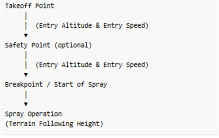
image-Jul-10-2026-09-00-43-7166-PM

During the spraying operation, the drone will switch to the configured terrain-following spraying height.

2. Return Flight Logic

When the drone finishes spraying or the tank becomes empty, the drone will:

  • Climb to the configured entry/exit altitude
  • Return to the takeoff point at the configured entry/exit altitude and speed
  • This behavior is the same whether a Safety Point (transfer point) is configured or not.

Return Flight Path

image (1)-4

3. Advantages of This Logic

This flight logic improves operational efficiency when entering or exiting the field, especially when:

  • the takeoff location contains low obstacles the operator wants to transit quickly to the working area large fields require long transit distances

4. Important Safety Notice (Power Lines)

If power lines exist within the field, operators must ensure:

  • The configured entry/exit altitude is lower than the height of the power lines
  • The upward radar is enabled
  • The operator visually confirms that the drone can safely pass under overhead lines Failure to properly configure altitude may lead to collision with overhead power lines.

5. Upcoming Logic Improvement

The R&D team is developing an optional flight logic selection that will allow operators to choose how the drone behaves between the Safety Point and the Breakpoint.

The operator will be able to select:

image (2)-3

This improvement will allow operators to optimize flight safety and efficiency based on field conditions.


Super User Issues Q&A and Version Upgrade – January 21 2026

Issue 1: Firmware Upgrade Stuck at 99%

Symptom

The firmware upgrade process gets stuck at 99%.

image (3)-2

Root Cause

After checking the logs, the R&D team found a software bug. In fact, the upgrade has already completed. Normally, after the upgrade finishes, the App should automatically terminate and restart. However, the new version does not perform this action, which causes the process to appear stuck at 99%.

Temporary Solution

When the upgrade reaches 99%:

  • Please wait 1 minute
  • Then restart the App or reboot the remote controller

The upgrade will be completed successfully.

This issue will be fixed in the next software release.

Issue 2: 5G Wi-Fi Instability

Symptom

If the customer’s Wi-Fi network is operating on the 5 GHz band, the remote controller may not be able to access the internet.

image (4)-1

Cause & Solution

The remote controller Wi-Fi mode is set to Auto by default. If it cannot connect to the network, you can manually select the Wi-Fi band:

Settings → Image Transmission → Channel Mode

Select 2.4 GHz or 5 GHz manually and choose the most stable option.

Latest Test Versions

  • App:
    3.0.2.9.ceresair
  • UAV Firmware:
    3.40.1.12.ceres

Upgrade Notes

  • During the upgrade, the progress may stop at 99%. This means the upgrade has already completed. Please wait 1 minute, then close the App or restart the remote controller.
  • After upgrading the App, two Ceres App icons may appear on the remote controller screen. Running version 3.0.2.9.ceresair will overwrite the old version. If it does not overwrite automatically, please manually delete the old App icon.
  • You can verify the installed version number in Device Management.
  • After the upgrade is completed, you may need to log in to the App again or re pair the drone with the remote controller.

image (5)-1


Quick Start or First-Time Setup Guide

C31 6x Battery Kit


V1.01

Quick Start or First-Time Setup Guide

  • Register a Ceres Server Account – Online
  • Log in to the Remote App and Update Software
    • Log in to the Ceres App using the registered account
    • Update the App to the latest version
  • Unbox/Assemble/Install Drone and Spray Base
    • Unbox and Assemble the drone and spray base
    • Ensure all cables are properly connected and secured.
    • Hot plugging of any cables, connectors, or modules is strictly prohibited.
  • How to Pair the Drone with the Remote
    • Power on the drone and Remote
    • Open the App and go to Settings → Remote Controller
    • Select Pair / Bind from the remote controller menu
    • Press and hold the drone battery button and observe the LED indicator
    • The drone and remote controller will pair automatically
  • Activate the Drone and Update Firmware
    • Enter the activation code in the App to activate the drone:
    • Ceres Drone Activation Code: UC5A0FE7
    • Follow the on-screen instructions to update the drone firmware to the latest version
  • Tank and flow meter calibration
    • Go to Start → Settings → Spray and follow the instructions to perform
    • Empty tank calibration
    • Full tank calibration
    • Flow meter calibration. (Note: Before calibrating the flow meter, use the upper-right button on the remote controller to perform pipeline purging, ensuring that all air is removed from the system. Make sure the Flow Coefficient value is around 100 (acceptable range: 90–110).

Important Notes

A stable and reliable internet or cell network connection is required when updating the App or drone firmware. Poor network connectivity may cause updating failures or firmware issues.

C31 Troubleshooting Manual V1.0

C31 Agricultural Drone Troubleshooting Manual (V1.0)

February 2026

Revision History

Version

Revision Date

Description

V1.0

1/16/2026

Testing Services Update

Avionics System

IMU Reporting Abnormalities

Fault Symptoms:

  1. Audible alert from the remote controller: “IMU not calibrated”
  2. Remote controller display shows IMU1 / IMU2 not calibrated

Possible Causes:

  1. Typically occurs after replacing the avionics assembly or interface board
  2. May also occur if the aircraft has not been powered on for an extended period

Troubleshooting Procedure:

  1. Place the aircraft on a level surface
  2. Ensure the environment is free of vibration and strong magnetic interference
  3. On the remote controller, navigate to:
    Aircraft Settings → Advanced Settings → IMU Calibration, and perform IMU calibration

GNSS Reporting Abnormalities

Fault Symptoms:

  1. Audible Warnings:
    1. Remote controller voice alert: “Dual-antenna heading abnormal”
  2. Visual Warnings:
    1. Weak GPS signal indication
    2. Satellite icon turns red or yellow
    3. Low number of satellites detected
    4. Positioning status icon flashing (e.g., green → red)
  3. Before Takeoff:
    1. The Applicator View App by Ceres Air indicates “Insufficient satellites, unable to take off” or “GPS not ready”
  4. During Flight:
    1. Aircraft drifting
    2. Unstable altitude
    3. Tendency toward loss of control

Possible Causes:

  1. Environmental Factors:
  2. Signal obstruction around the aircraft (e.g., high-rise buildings, indoor environments, dense forest canopy)
    1. Weather Interference:
      1. Thunderstorms or ionospheric disturbances affecting signal transmission
    2. Electromagnetic Interference:
      1. Operation near high-voltage power lines, communication base stations, radar installations, or other strong electromagnetic sources
    3. Hardware Factors:
      1. Physical damage to antennas (e.g., impact damage from a crash)
      2. Loose antenna connectors or damaged antenna cables

Troubleshooting Procedure:

  1. Before flight, confirm the operating area is open and unobstructed
  2. Pause flight operations and wait for weather conditions to stabilize
  3. Fly away from known interference sources
  4. Inspect antenna condition and cable connections; replace damaged components as necessary

Avionics Indicator Light Definitions

Propulsion System

Motor and Mechanical Failures

Fault Symptoms:

  1. Rough or restricted rotation, accompanied by a grinding or scraping noise
  2. Severe vibration during motor startup, with the motor unable to rotate normally
  3. Visible motor housing deformation, leading to bearing wear or damage

Possible Causes:

  1. Sand, dust, or foreign objects entering the motor interior
  2. Impact, compression, or collision during flight or transportation, causing motor housing deformation
  3. Troubleshooting Procedure:
    1. Promptly clean foreign objects from the motor interior
    2. Replace the motor if mechanical damage or deformation is detectedCauses of failure:

Motor Overheating

Fault Symptoms:

  1. Motor housing is too hot to touch, with the remote controller indicating a temperature exceeding 140 °F (60 °C)
  2. Presence of a burnt or scorched odor from the motor

Possible Causes:

  1. Prolonged operation under overload conditions, such as heavy payloads, high RPM, or high ambient temperatures

Troubleshooting Procedure:

  1. Land immediately and allow the motor to cool down
  2. Inspect the motor windings for discoloration or deformation
  3. Reduce payload and monitor motor temperature during subsequent flights

Propeller Faults

Fault Symptoms:

  1. Severe vibration during flight with a noticeable increase in noise
  2. Unstable hover with irregular lateral drift
  3. Visible propeller damage, including cracks, delamination, or deformation
  4. Possible Causes:
    1. Impact or compression during operation or transportation, resulting in propeller deformation
    2. Improper installation, such as insufficient tightening of propeller clamp bolts, causing centrifugal imbalance
    3. Surface contamination, including mud, pesticide residue, or corrosive chemical buildup

Troubleshooting Procedure:

  1. Replace propellers with new units

⚠️ C31 propellers must be replaced in matched pairs

  1. Verify propeller clamp bolt torque
  2. Clean propeller surfaces to remove dirt and chemical residue

Power Unit Communication Failure

Fault Symptoms:

  1. After power-on, the ESC status LED on the affected arm displays a purple color
  2. On the remote controller interface, under Propulsion System Status, the affected arm is shown as “Not Recognized”
    1. (Example: Arm No. 2)

Possible Causes:

  1. The flight controller is not receiving communication signals from the ESC

Troubleshooting Procedure:

  1. Verify that all related wiring harnesses are properly connected, fully seated, and undamaged
  2. Check connectors for looseness, bent pins, or corrosion
  3. If the issue persists, replace the motor and/or ESC on the affected arm

Loose or Disconnected Wiring Harness Conditions

This section describes typical fault symptoms caused by loose or disconnected wiring harnesses. Different harness faults may result in specific LED indications, system status messages, and subsystem recognition failures.

Flight Controller / CAN Bus Harness is loose

Fault Symptoms:

  1. Navigation LEDs on Arms 1–4 remain solid purple
  2. Control signals lostRemote controller cannot connect to
  3. the aircraft

Troubleshooting Procedure:

  1. Verify that all related wiring harnesses are properly connected, fully seated, and undamaged
  2. Check connectors for looseness, bent pins, or corrosion

Battery Signal Harness – Loose

Fault Symptoms:

  1. Navigation LEDs on Arms 1–4 remain solid purple
  2. Remote controller cannot connect to the aircraft

Troubleshooting Procedure:

  1. Verify that all related wiring harnesses are properly connected, fully seated, and undamaged
  2. Check connectors for looseness, bent pins, or corrosion

Downward Radar Harness – Loose:

Fault Symptoms:

  1. Remote controller connects normally
  2. Radar System displays “Downward Radar Not Recognized”

Troubleshooting Procedure:

  1. Verify that all related wiring harnesses are properly connected, fully seated, and undamaged
  2. Check connectors for looseness, bent pins, or corrosion

Arm No. 1 Harness – Loose

Fault Symptoms:

  1. ESC LED indicators:
    1. Arm 1: Purple
    2. Arm 2: Red
    3. Arms 3 & 4: Green
  2. Power System displays Motors No. 1 and No. 5 Not Recognized:

Troubleshooting Procedure:

  1. Verify that all related wiring harnesses are properly connected, fully seated, and undamaged
  2. Check connectors for looseness, bent pins, or corrosion

Arm No. 2 Harness – Loose

Fault Symptoms:

  1. ESC LED indicators:
    1. Arm 2: Purple
    2. Arm 1: Red
    3. Arms 3 & 4: Green
  2. Power System displays Motors No. 2 and No. 6 Not Recognized

Troubleshooting Procedure:

  1. Verify that all related wiring harnesses are properly connected, fully seated, and undamaged
  2. Check connectors for looseness, bent pins, or corrosion

Arm No. 3 Harness – Loose

Fault Symptoms:

  1. ESC LED indicators:
  2. Arm 3: Purple
  3. Arms 1 & 2: Red
  4. Arm 4: Green
  5. Power System displays Motors No. 3 and No. 7 Not Recognized

Troubleshooting Procedure:

  1. Verify that all related wiring harnesses are properly connected, fully seated, and undamaged
  2. Check connectors for looseness, bent pins, or corrosion

Arm No. 4 Harness – Loose

Fault Symptoms:

  1. ESC LED indicators:
    1. Arm 4: Purple
    2. Arms 1 & 2: Red
    3. Arm 3: Green
  2. Remote controller connects normally
  3. Power System displays Motors No. 4 and No. 8 Not Recognized

Troubleshooting Procedure:

  1. Verify that all related wiring harnesses are properly connected, fully seated, and undamaged
  2. Check connectors for looseness, bent pins, or corrosion

Front camera harness - Loose

Fault Symptoms:

  1. Remote controller connects normally
  2. Vision System displays “Front Camera Not Connected”

Flight Controller PWM1 Harness - Loose

Fault Symptoms:

  1. ESC status:
    1. Arms 1–3: ESC fault
    2. Arm 4: ESC normal
  2. ESC LED indicators:
    1. ESCs No. 1–6: Purple
    2. ESCs No. 7 & 8: Green
  3. Remote controller connects normally
  4. Power System displays Motors No. 1–6 Not Recognized

Troubleshooting Procedure:

  1. Verify that all related wiring harnesses are properly connected, fully seated, and undamaged
  2. Check connectors for looseness, bent pins, or corrosion

Flight Controller PWM2 Harness – Loose

Fault Symptoms:

  1. ESC status:
    1. Arm 4: ESC fault
    2. Arms 1–3: ESC normal
  2. ESC LED indicators:
    1. Arms 1 & 2: Red
    2. Arm 3: Green
    3. Arm 4: Purple
  3. Remote controller connects normally
  4. Power System displays Motors No. 7 and No. 8 Not Recognized

Troubleshooting Procedure:

  1. Verify that all related wiring harnesses are properly connected, fully seated, and undamaged
  2. Check connectors for looseness, bent pins, or corrosion

Flight Controller Perception / Ethernet Harness – Loose

Fault Symptoms:

  1. Remote controller connects normally
  2. Vision System and Radar System not recognized
  3. Vision System displays “Front Camera Not Recognized”

Troubleshooting Procedure:

  1. Verify that all related wiring harnesses are properly connected, fully seated, and undamaged
  2. Check connectors for looseness, bent pins, or corrosion

Rear Radar Harness – Loose

Fault Symptoms:

  1. Remote controller connects normally
  2. Radar System displays “Rear Radar Not Recognized”

Troubleshooting Procedure:

  1. Verify that all related wiring harnesses are properly connected, fully seated, and undamaged
  2. Check connectors for looseness, bent pins, or corrosion

Payload Control (Lifting Module) Harness – Loose

Fault Symptoms:

  1. Remote controller connects normally
  2. Lifting System displays “Not Recognized”

Troubleshooting Procedure:

  1. Verify that all related wiring harnesses are properly connected, fully seated, and undamaged
  2. Check connectors for looseness, bent pins, or corrosion

Front Radar Harness – Loose

Fault Symptoms:

  1. Remote controller connects normally
  2. Radar System displays “Rotating Radar Not Recognized”

Troubleshooting Procedure:

  1. Verify that all related wiring harnesses are properly connected, fully seated, and undamaged
  2. Check connectors for looseness, bent pins, or corrosion

Front / Rear Power Distribution Board Signal Harness – Loose

Fault Symptoms:

  1. Battery cannot detect load
  2. Aircraft cannot power on
  3. Red indicator LED flashes briefly and then turns off

Troubleshooting Procedure:

  1. Verify that all related wiring harnesses are properly connected, fully seated, and undamaged
  2. Check connectors for looseness, bent pins, or corrosion

Front Power Distribution Board Front/Rear Power Harness – Loose

Fault Symptoms:

  1. ESC indicators on the affected ports do not illuminate
  2. Power System displays corresponding motors as “Not Recognized”

Troubleshooting Procedure:

  1. Verify that all related wiring harnesses are properly connected, fully seated, and undamaged
  2. Check connectors for looseness, bent pins, or corrosion

Vision system

Image Transmission (Video Link) Failure

Fault Symptom:

  1. The remote controller displays a warning: “Vision System Fault – Image Transmission Not Detected.”

Possible Causes:

  1. Damaged image transmission antenna (bent, broken, or physically damaged)
  2. Loose antenna connection or poor electrical contact

Troubleshooting Steps:

  1. Inspect the image transmission antenna for damage
  2. Tighten the antenna connection securely
  3. Replace the image transmission antenna if damage is found

Front Camera Failure

Fault Symptoms:

  1. The remote controller displays a vision system warning: “Front Camera Not Detected.”
  2. Blurred image, black screen, or snow/noise artifacts
  3. Gimbal cannot rotate normally or video image shakes excessively

Possible Causes:

  1. Physical damage caused by collision (loose or broken wiring harness)
  2. Scratched lens or water ingress
  3. Abnormal connection between the image transmission module and the camera
  4. Ethernet connection failure

Troubleshooting Steps:

  1. Inspect the connection path: front interface board → signal cables → camera
    Replace the front interface board and/or camera if necessary2
  2. Gently wiggle the camera cable connectors (power off before operation) to check for looseness. Replace the front camera if the issue persists
  3. If hardware damage is confirmed (e.g., cracked lens or broken cable), replace the affected components immediately

Lifting system

Lifting System Reporting Abnormality

Fault Symptoms:

  1. After a crash, the lifting system is displayed as “Not Detected” on the aircraft or remote controller.

Possible Causes:

  1. High-altitude crash resulting in damage to the lifting system or lifting module.

Troubleshooting Steps:

  1. Inspect the payload control wiring harness and lifting module wiring connectors for abnormal conditions.
  2. If looseness or poor contact is found, power off the aircraft before tightening the connectors.
  3. If the issue cannot be resolved after reconnection, it is recommended to replace the lifting control wiring harness or the lifting module.

Anti-Sway System Reporting Abnormality

Fault Symptoms:

  1. During lifting operations, the payload shows no anti-sway effect and continues to swing violently.

Possible Causes:

  1. Power supply failure to the anti-sway module, preventing normal operation.
  2. Software malfunction in the anti-sway module, causing failure to execute the anti-sway algorithm.

Troubleshooting Steps:

  1. First, check whether the anti-sway module wiring harness is properly connected.
  2. If the connection appears normal, power off the aircraft and re-plug the wiring harness to attempt recovery.
  3. If reconnection does not resolve the issue, reinstall or update the anti-sway module software, or replace the anti-sway module if necessary.

Weighing Sensor Reporting Fault-Weighing Sensor Not Detected

Fault Symptoms:

  1. After power-on, the system displays: “Operation System – Weighing Sensor Not Detected.”

Possible Causes:

  1. High-altitude crash resulting in weighing sensor damage.
  2. Water ingress causing sensor failure.

Troubleshooting Steps:

  1. Replace the weighing sensor with a new unit.

Weighing Sensor Reporting Fault-Weighing Not Calibrated

Fault Symptom:

  1. The system displays a weighing calibration error.

Possible Cause:

  1. Weighing calibration was not performed after replacing the anti-sway module.

Troubleshooting Steps:

  1. Perform empty-load calibration or full-load calibration in the operation system interface.

Weighing Sensor Reporting Fault-Measured Weight Does Not Match Actual Load

Fault Symptom:

  1. The displayed weight value does not match the actual payload weight.

Possible Causes:

  1. Calibration-related error.
  2. Weighing sensor malfunction.

Troubleshooting Steps:

  1. Perform empty-load calibration with no lifting rope or payload attached.
  2. If the weight value remains incorrect after calibration, replace the weighing sensor.

Radar system

Radar Hardware–Related Faults

Fault Symptom:

  1. The remote controller displays “Radar System Not Detected – Rotating Radar ESC.”

Possible Causes:

  1. Radar ESC failure

Troubleshooting Procedure:

  1. Replace the rotating radar assembly

Fault Symptom:

  1. The remote controller displays: “Radar System Not Detected – Rotating Radar Altitude Hold.”

Possible Cause:

  1. Failure of the radar internal PCB

Troubleshooting Procedure:

  1. Replace the rotating radar assembly

Fault Symptom:

  1. The remote controller displays: “Radar System Not Detected – Rotating Radar Obstacle Avoidance.”
  2. Abnormal noise is heard during rotation, and intermittent radar errors are reported.

Possible Cause:

  1. Loose radar mounting cover

Troubleshooting Procedure:

  1. Replace the rotating radar assembly

Fault Symptom:

  1. The remote controller displays: “Radar System Not Detected – Rear Obstacle Avoidance Radar.”

Possible Cause:

  1. Rear obstacle avoidance radar failure

Troubleshooting Procedure:

  1. Replace the rear obstacle avoidance radar module

Fault Symptom:

  1. The remote controller displays: “Radar System Not Detected – Downward Radar.”

Possible Cause:

  1. Downward-facing radar failure

Troubleshooting Procedure:

  1. Replace the downward radar module

Software Version–Related Faults

Fault Symptoms:

  1. After powering on the aircraft, the system displays: “Radar System Fault – Radar Not Rotating.”

Possible Causes:

  1. Firmware version mismatch between the aircraft and the newly installed radar module

Troubleshooting Procedure:

  1. Upgrade to the latest firmware version
  2. Ensure the remote controller firmware version matches the aircraft firmware version

Other Radar-Related Faults

Fault Symptoms:

  1. Intermittent radar faults with various abnormal error reports

Possible Causes:

  1. Excessive aircraft vibration causing unstable radar connections

Troubleshooting Procedure:

  1. Adjust propeller clamp tightness to ensure consistency
  2. Secure radar connectors using adhesive (yellow glue)

Fault Symptom:

  1. Radar system not detected, accompanied by a front camera fault

Possible Cause:

  1. Excessive aircraft vibration causing Ethernet communication instability

Troubleshooting Procedure:

  1. Inspect and secure Ethernet connections

Fault Symptom:

  1. The remote controller announces: “Radar System Fault – Rear Obstacle Avoidance Not Detected.”

Possible Causes:

  1. Firmware version mismatch between the radar and aircraft
  2. Radar malfunction

Fault Symptom:

  1. Rear radar hardware failure

Possible Cause:

  1. Possible causes include incompatible radar firmware, a poor connection to the rear radar, or a faulty radar unit.

Troubleshooting Procedure:

  1. Inspect rear radar connections
  2. Verify aircraft firmware and remote controller firmware versions
  3. Upgrade to the latest firmware
  4. If the rear radar is still not detected, replace the rear radar assembly

Frame Module

Front Interface Board Faults

Fault Symptoms:

  1. After the battery is powered on, the flight controller does not power up (wiring harness connections are confirmed to be normal)

Possible Causes:

  1. Battery communication failure on the front interface board

Troubleshooting Procedure:

  1. Inspect the battery communication wiring
  2. If wiring is normal, replace the front interface board

Fault Symptom:

  1. After powering on the aircraft, the propulsion system is not recognized, and the ESC indicator lights display purple

Possible Causes:

  • ESC signal interface damage (e.g., bent or broken connector pins)

Troubleshooting Procedure:

  • Replace the front interface board

Barometer Faults

Fault Symptom:

  1. After powering on the aircraft, the system displays: Frame Module Fault – Barometer Error.”

Possible Cause:

  1. Barometer malfunction or failure within the frame module

Troubleshooting Procedure:

  1. Inspect barometer connections
  2. Replace the barometer module or the affected frame module component if necessary

Communication Faults

Fault Symptom:

  1. The propulsion system is not recognized, and the ESC indicator lights display purple

Possible Causes:

  1. Communication failure in the corresponding arm module

Troubleshooting Procedure:

  1. Inspect the communication wiring harness of the affected arm
  2. If the wiring is normal, replace the front interface board

Fault Symptom:

  1. After powering on the aircraft, multiple faults are reported simultaneously, such as:
    “Vision System Fault,” “Radar System Fault,” and other related errors

Possible Cause:

  1. CAN bus short circuit within the aircraft

Troubleshooting Procedure:

  1. Disconnect all external payloads and accessories
  2. Retain only the following connections:
    1. Avionics (flight controller)
    2. Ethernet
    3. Battery communication
    4. Power distribution board (PDB) signal harness
  3. Power on the aircraft:
    1. If the aircraft powers on normally, reconnect additional devices one by one until the shorted device is identified
  4. If the aircraft still fails to power on with only the above connections:
    1. Troubleshoot sequentially following this order:
      Front interface board → wiring harness → avionics
    2. Continue troubleshooting until the aircraft powers on normally, then resume the above isolation procedure

Fault Symptom:

  1. After powering on the aircraft, the status LED flashes red slowly and then turns off

Possible Causes:

  1. Battery load not detected
  2. Load detection module failure

Troubleshooting Procedure:

  1. Inspect the battery signal wiring connection
  2. Attempt to power on using Battery No. 2
  3. If the aircraft powers on normally, replace the upper cover assembly of Battery No. 1
  4. If the issue persists:
    1. Inspect the PDB signal wiring
    2. If wiring is normal, replace the power distribution board assembly

Power System

Battery Faults

Fault Symptom:

  1. The remote controller announces: “Power System Fault – Battery Cells Not Detected.”

Possible Cause:

  1. Battery communication failure
  2. Power distribution board (PDB) communication failure

Troubleshooting Procedure:

  1. Replace the battery and attempt to power on the aircraft
  2. If the issue persists, replace the power distribution board

Fault Symptom:

  1. The remote controller announces: “Power System Fault – Abnormal Cell Voltage Difference, Please Land Immediately.”

Possible Cause:

  1. Excessive voltage imbalance between battery cells

Troubleshooting Procedure:

  1. Upload the battery log
  2. Await analysis results from engineering support

Fault Symptom:

  1. Abnormal voltage jumps occur during charging or discharging
    (e.g., voltage suddenly increases during charging, or drops suddenly when installed on the aircraft)

Possible Cause:

  1. Excessive voltage imbalance between battery cells

Troubleshooting Procedure:

  1. Upload the battery log
  2. Await analysis results from engineering support

Flight Authorization

Flight Authorization

Fault Symptom:

  1. The remote controller displays “Flight Authorization Error”

Possible Cause:

  1. The remote controller is logged in with a non-owner aircraft account
  2. Aircraft unlocking is restricted

Troubleshooting Procedure:

  1. Log in to the Ceres Aviation platform
  2. Grant control authorization to the relevant account under Flight Control Authorization

Pilot Authorization

Fault Symptom:

  1. The remote controller displays “Pilot Authorization Error”

Possible Cause:

  1. The pilot has not completed official Ceres training
  2. Pilot credentials have not been approved or verified

Troubleshooting Procedure:

  1. Contact the authorized dealer or Ceres technical support
  2. Complete required pilot training and certification review

Drone status

Fault Symptom:

The remote controller displays: “Aircraft Status Error”

Possible Cause:

  1. The current operating area does not permit aircraft unlocking (e.g., restricted or no-fly area outside the dealer’s authorized operating region) outside the dealer’s authorized operating region)

Troubleshooting Procedure:

  1. Submit required documentation to request area unlocking
  2. Coordinate with Ceres technical support to add an approved test flight zone for the aircraft

C31 Maintenance & Service Manual V1.1

Maintenance manual

V1.1

Ceres Air LLC

January 2026

Revision record


version


Revision date


Revision department


Modify the description


V1.0


2025.12.30


Testing Services Department


First release


Notice to Users

  1. Maintenance Requirement
    The aircraft must be operated, maintained, and serviced strictly in accordance with the instructions set forth in this Maintenance Manual, including all routine and scheduled maintenance requirements. Failure to properly perform such maintenance may void the applicable warranty. The Company reserves the right to request and review maintenance records at any time. Warranty coverage and service eligibility may be denied if the aircraft has not been maintained in accordance with the requirements of this manual.
  2. Exclusion of Indirect and Consequential Damages
    The Company shall not be liable for any indirect, incidental, consequential, or special damages, whether foreseeable or not. This includes, without limitation, downtime costs, loss of use, loss of labor, travel expenses, transportation costs, handling fees, communication expenses, loss of business, loss of profits, reputational damage, or any other related or consequential losses.
    For personal injury or property damage to third parties arising from improper operation or misuse of the aircraft, the Company shall not be responsible for any damages exceeding applicable insurance coverage.
  3. Consumables and Excluded Causes
    Consumable parts and wear-and-tear items are not covered under warranty. The Company shall not provide warranty coverage or compensation for damage or subsequent failures caused by force majeure, accidents, external forces, improper operation, misuse, abuse, or operation outside of normal or intended use.
  4. Use of Authorized Parts Only
    Only original or Company-authorized parts and components may be used with the aircraft. The Company shall not be liable for any damage, malfunction, or loss resulting from the use of non-original or unauthorized parts.
  5. No Liability for Unauthorized Modifications
    The Company shall not be responsible or liable for any damage, failure, or loss resulting from unauthorized modifications, alterations, retrofits, or additions to the aircraft or its components.

Notice to Users

Dear Valued Customer:

Thank you for purchasing our unmanned aircraft product. This Maintenance Manual defines the establishment and termination of warranty responsibilities, as well as the rights and obligations related to after-sales service between the Company and the user.

Upon receipt of the aircraft, please be sure to carefully read this manual before operating the product.

This Maintenance Manual serves as proof for submitting quality or warranty claims to the Company and must be properly retained. The manual must be presented for warranty service.

This manual is provided with the equipment, one copy per aircraft, and shall be regarded as a permanent component of the aircraft. When the aircraft is sold or transferred, this manual shall be transferred together with the aircraft.

Due to regulatory changes, technological improvements, or performance upgrades, the Company reserves the right to modify the design and technical specifications of its aircraft models at any time without prior notice for units already sold.

If any issues occur, please contact the nearest authorized service station, authorized dealer, or call the service hotline at +1 (314) 887-4999.

When repairs are performed by an authorized dealer, please provide this manual to the service station for completion of the Maintenance Record Card.

Note: The contents and technical specifications in this manual were valid at the time of printing. The Company reserves the right of final interpretation in case of changes.

Maintenance agreement

Basis and purpose

Regular maintenance of agricultural unmanned aircraft is essential to maintain proper technical condition, reduce failures, ensure safe operation, and extend service life.

Maintenance grading

Maintenance is divided into daily maintenance and regular maintenance.

Routine maintenance

Daily maintenance refers to routine inspections and cleaning performed before and after each flight operation.

Regular maintenance

  1. Scheduled maintenance refers to maintenance activities centered on cleaning, tightening, inspection, and replacement of safety-related components beyond daily maintenance.
  2. Maintenance interval: every three months or every 400 flight missions or 200 agricultural tons, whichever occurs first.
  3. Users may choose between minor or major maintenance programs recommended by the Company to ensure optimal operating condition and extended service life.

Daily Maintenance

Maintenance cycle system Components Daily maintenance items
Before daily operations Propulsion system propeller Propeller clamp Check for damage, gaps in the propeller spacers, and loose screws
  motor Check whether there is any gap between the motor base and the adapter, and whether excessive movement is present  
  ESC Check whether the ESC surface is damaged and whether the mounting screws are loose.  
  Frame system Frame
Arm
Check whether the airframe and arm mounting screws are loose or damaged.
  Arm lock Check whether the arm locking mechanism is intact, whether there is any offset gap during folding, and whether excessive movement is present.  
  Spray System Pump Check the pump for abnormal noise or leakage, and verify that the wiring harness is not loose.
  Flowmeter Check the interior of the flow meter for foreign objects or leakage, and verify that the wiring is not loose or damaged.  
  Nozzle Check the nozzles for abnormal noise or leakage, and verify that the wiring is not loose or damaged. Check whether the spray disc is damaged or excessively worn  
  Weigh
Components
Check whether the sensor housing is intact, and whether the wiring is loose or damaged.  
  Hoses and connectors Check for any damage or excessive wear.  
  Disc assembly Check whether the spray disc is damaged and whether the locking screws are loose.  
  Cargo system Sling Check whether the spray disc is damaged and whether the locking screws are loose.
  Hook Check whether the hook is deformed, worn, or cracked  
  Lifting
Pendulum components
Check whether the sensor housing is intact, and whether the wiring is loose or damaged  
  Spreading system Auger Check for excessive wear.
  Spreader Check whether the spreader operates normally, whether there is any abnormal noise, and whether the wiring is loose or damaged  
  Lidar system radar
module
Check whether the radar surface is contaminated with debris or foreign matter
  Battery battery Check whether the battery charge level is sufficient.
  Avionics system RTK
Antenna
Check whether the antenna is damaged
  Image Transmission Antenna Check whether the antenna is damaged  
  Avionics
module
Check whether the avionics equipment surfaces are contaminated with debris or foreign matter.  
  Distribution board assembly Check whether the power distribution board connectors are worn, and whether the locating pins and battery latches are damaged.  
  Remote controller Remote control Check whether the remote controller battery charge level is sufficient.
  Charger charger Check whether all charger functions operate properly and whether the charger connectors are worn
After daily operations Daily cleaning Cleaning of the lifting device After operations are completed, clean the lifting (hoisting) system
  Airframe Cleaning After operations are completed, clean the airframe surfaces  


Key operation methods for daily maintenance

Airframe inspection

Visual inspection: Before operating every day, carefully check the appearance of the drone。

Inspection Areas:

  1. Check whether the airframe has any cracks, deformation, or damage
  2. Check the connection points between the arms and the airframe
  3. Check the landing gear mounting points

If any damage to the airframe is detected, operation shall be stopped immediately and the affected components shall be repaired or replaced. After the operation is completed, re-inspect the airframe to determine whether any new damage occurred during flight

Radar Inspection:
Check the radar for any external damage or contamination. No foreign objects are permitted on the radar surface, including stickers or residue.

Fastener Tightening: Inspect all fasteners on the airframe one by one to ensure that they are properly tightened and free from looseness. Where fasteners are fitted with mechanical stops or limiters, verify carefully that each fastener is fully seated and tightened to its specified position

Inspection Area:

  1. Arm connection components
  1. Battery mounting bracket and airframe
  1. Propeller clamp connections
  1. Locking screws

If any fastener is found to be loose, it shall be removed, thread-locking compound shall be reapplied, and the fastener shall be re-tightened. This is required to prevent component detachment caused by loose fasteners, which may result in a flight accident.

Propulsion System Maintenance

Motor Inspection:
Manually rotate the motor and check whether the rotation is smooth, with no binding, hesitation, or abnormal resistance. At the same time, listen to the motor while it is operating. Under normal conditions, the motor should run smoothly and quietly. If sharp noise or other abnormal sounds are present, this may indicate a motor fault and further inspection or replacement is required.

Inspect the motor surface for signs of wear or discoloration caused by overheating. If any abnormal condition is found, the root cause shall be promptly investigated, which may include excessive motor load, inadequate cooling, or other related issues.

Manually move the propeller up and down. If inconsistent gaps are observed between the motor and the motor base, promptly contact the nearest authorized service center;

Press the propeller clamp by hand. If any gap appears between the motor and the adapter, immediately contact the nearest authorized service center;

Propeller Inspection:
Inspect the propellers for any cracks, chips, or deformation. Even minor cracks may cause the propeller to fracture during high-speed rotation, potentially resulting in serious accidents. Check that the connection between the propeller root and the propeller clamp is secure. If any looseness is found, re-tighten as required.

Additionally, ensure that the propeller surfaces are clean and free of foreign material. If dust, dirt, or debris is present, gently remove it using a soft-bristle brush.

ESC Inspection:
Inspect the ESC surface for contamination, signs of water ingress, or evidence of overheating or burn marks. Check whether the ESC mounting bracket has any cracks. The ESC is a critical component responsible for controlling motor speed; any malfunction may affect the flight stability of the aircraft.

If any abnormal condition is found on the ESC, do not attempt to disassemble it. Contact qualified service personnel or an authorized service center for inspection and repair.

Lifting System Maintenance

Hook and Connection Component Inspection:
Inspect the hook for any deformation, wear, or cracks, with particular attention to load-bearing areas. Inspect the ropes, chains, and other components connecting the hook to the aircraft for any breakage, disengagement, or excessive wear.

Lifting Load Cell (Weighing Sensor):
Inspect the sensor housing to ensure it is intact, and check whether the wiring connections are loose or damaged. Verify the accuracy of the lifting load measurement through no-load and loaded tests. Abnormal sensor data may result in overload conditions during lifting operations, posing a serious flight safety risk. If any abnormality is detected, the sensor shall be calibrated or replaced in a timely manner.

Tare Calibration:
Place the aircraft on a flat and level surface, ensuring that no lifting load is attached, and perform tare (zero) calibration.

Weight Calibration:
Lift the aircraft onto a stable stand capable of supporting its weight, ensuring the aircraft remains level. Suspend a 110lb(50 kg) calibration weight (weights in the range of 44lb-176lb(20–80 kg) may be used). Enter the actual suspended weight into the remote controller accordingly.

Spray System Maintenance

Pump:
Check the pump for abnormal noise or excessive vibration. Inspect for water leakage or blockage. Check the pump check-valve assembly for any leakage or damage.

Filter:
Check the filter for blockage or damage, and clean or replace it in a timely manner.

Centrifugal Nozzle:
Check whether the spray disc is damaged. Clean the nozzle and inspect it for any signs of corrosion.

Control Box Assembly:
Check whether the unit powers on normally and whether all functions operate correctly. Clean the assembly and inspect it for any signs of corrosion.

Load Cell (Weighing Sensor):
Inspect the sensor housing to ensure it is intact, and check whether the wiring connections are loose or damaged. Verify that the sensor can accurately measure weight through no-load and loaded tests.

Flow Meter:
Clean the flow meter and inspect it for any signs of corrosion. Check whether it powers on normally and whether all functions operate correctly.

Important Note:
After each operation, the spray system shall be thoroughly cleaned using clean water circulation and a neutral cleaning agent to prevent corrosion of components caused by pesticide residue.

Battery Maintenance

Proper maintenance and care of lithium batteries ensure reliable performance and extend battery service life.

Lithium Battery Care:
Wipe the exterior of the lithium battery with a clean towel. Clean the battery terminals using a cotton swab and alcohol. If discoloration, blackening, or corrosion is observed on the battery terminals, the battery shall not be reused, and after-sales service personnel shall be contacted. When handling lithium batteries, ensure that hands and fingers are clean and dry to prevent sweat or moisture from entering the battery.

Clean the power distribution board terminals using alcohol. If any blackening or corrosion is observed, the component shall not be reused and after-sales service personnel shall be contacted.

Lithium Battery Storage Requirements:
Lithium batteries shall be stored at a state of charge of 50%–65%, or at a battery voltage of 64.8 V–70.2 V. Do not store batteries for long periods after they have been fully discharged, as this may cause over-discharge and result in cell damage.

Lithium batteries intended for long-term storage (more than three months) shall be stored in an environment with a temperature of 15 °C ±5 °C (59 °F ±9 °F) and a relative humidity of 65% ±10% RH. During long-term storage, perform at least one maintenance charge every three months. Battery storage shall strictly comply with the above requirements.

Regularly inspect the condition of lithium batteries. If excessive heating or other abnormal conditions are observed, promptly contact after-sales service personnel for handling.

Lithium Battery Recycling:
Used batteries contain various heavy metals, including mercury, manganese, cadmium, lead, zinc, and nickel. When discarded improperly, battery casings may gradually corrode, allowing heavy metals to leach into soil and water, causing environmental pollution. If crops grown in contaminated soil or contaminated water are consumed, these toxic heavy metals may accumulate in the human body and pose serious health risks.

The Company will, in accordance with national regulations and industry policies, guide authorized dealers and users to actively carry out the recycling of used lithium batteries in compliance with local battery recycling regulations

Note: If the battery charge level drops to 0%, the battery will be locked. Please promptly contact your local authorized dealer for assistance

Cleaning Maintenance

Airframe Cleaning:
Use a soft, dry cloth or a soft-bristle brush to gently wipe the airframe and remove dust, dirt, and debris from the surface. For stubborn stains, a small amount of clean water or a dedicated cleaning agent may be used. Take care to prevent moisture from entering internal electronic components. Pay special attention to areas where dust tends to accumulate, such as motor cooling vents, propeller roots, and airframe gaps.

Spray System Cleaning

  • Basic Cleaning (After Operation)
  • Step 1: Drain Residual Liquid
    Open the drain valve at the bottom of the chemical tank and completely drain any remaining liquid to prevent residue buildup.
  • Step 2: Clean Water Rinse
    Fill the tank with approximately one-third of its capacity with clean water. Activate the spray system and circulate for 1–2 minutes, then drain. Repeat this process 2–3 times until the discharged water shows no pesticide color or odor.
  • Step 3: Local Wiping
    Use a soft-bristle brush (to avoid scratching the inner surface of the tank) to clean the tank inlet at the top and the corners of the inner walls. Rinse thoroughly with clean water.
  • Deep Cleaning (When Changing Chemicals / Long-Term Storage)

Step 1: Neutral Cleaning Agent Circulation
Fill the tank with approximately one-quarter of its capacity with clean water mixed with a neutral detergent diluted at a ratio of 1:50. Activate the spray system and circulate for 3–5 minutes to fully dissolve residual chemicals, then drain.

Step 2: Secondary Clean Water Rinse
Fill with clean water and circulate twice to ensure all cleaning agent residue is completely removed, then drain.

Step 3: Drying
Open the tank lid and place the tank in a well-ventilated, dry area to air-dry (avoid direct sunlight), or use clean, dry compressed air to dry the inner walls to prevent moisture retention and corrosion.

Lifting System Cleaning:
Remove dirt and debris from lifting system components such as hooks, ropes, and chains to prevent corrosion or interference with normal operation. For connection points that use lubricants, apply an appropriate amount of lubricant after cleaning to ensure smooth movement of the components

Scheduled Maintenance

After completing daily maintenance, the C31 agricultural unmanned aircraft shall undergo scheduled maintenance within fixed intervals based on calendar time, cumulative flight hours, or operating workload/acres cover, whichever occurs first.

Specific maintenance items and intervals are detailed in the table below.

“★” indicates inspection, tightening, cleaning, or similar maintenance actions.

“■” indicates component replacement.

Module Maintenance   Scheduled        
  Maintenance Interval ((X 1 week) 1 4 12 26 52  
  Operating Time(X 1 Hour) 20 50 100 250 500  
Wear Parts Replacement & Inspection Propellers
  Propeller Clamps  
  Spacers / Washers  
Airframe Frame Inspect the front frame for cracks, damage, or structural looseness
  Inspect the left and right frames for cracks, damage, or structural looseness  
  Inspect the rear frame for cracks, damage, or structural looseness  
  Check whether frame mounting screws are loose or broken  
  Joints Inspect inner and outer joints for cracks, damage, or looseness
  Inspect carbon tubes for cracks, damage, or looseness  
  Inspect joint shafts for cracks, damage, or looseness  
  Check fasteners for joints, carbon tubes, and shafts for looseness or breakage  
Air frame Landing Gear Check whether landing gear-to-frame screws are loose or broken
  Check whether landing gear-to-body screws are loose or broken  
  Inspect landing gear for deformation or excessive wobble  
  Frame Accessories Inspect battery mounting brackets for excessive wear or deformation
  Inspect propeller holder brackets for excessive wear or deformation  
  Inspect frame wiring harnesses for damage, loose connectors, or seal deformation  
Spraying System Water Pump Check for abnormal noise or leakage, and whether wiring harness is loose
  Flowmeter Check for foreign objects or leakage, and whether wiring is loose or damaged
  Nozzles Check for abnormal noise or leakage, and whether wiring is loose or damaged
  Weighing Module Inspect sensor appearance, wiring looseness, or damage
  Tubing & Connectors Inspect for damage or excessive wear
  Spray Disc Assembly Inspect for damage, and check whether locking screws are loose
Spreading System Auger Inspect for excessive wear
  Spreader Check for abnormal noise, proper functionality, and wiring condition
Perception System FPV Camera Inspect and clean for corrosion
  Verify power-on and normal functionality  
  Radar/LiDAR Inspect and clean for corrosion
  Verify power-on and normal functionality  
Power System Motor Check whether motor top cover and shaft are loose
  Check whether mounting screws are loose  
  Inspect motor terminals for breakage  
  Check whether motors show axial movement or misalignment  
  Verify motor tilt angle is correct  
  ESC Inspect ESC surface cleanliness
  Check whether ESC mounting screws are loose or broken  
Remote Controller Remote Controller Inspect and clean for corrosion
  Verify power-on and normal functionality  
Charger Charger Inspect and clean for corrosion
  Verify power-on and normal functionality  
Lithium Battery / Generator   Perform routine maintenance and scheduled servicing in accordance with the maintenance cycles specified for lithium batteries and generators.          


Scheduled Maintenance Items

Minor maintenance shall be performed once per month, and major maintenance shall be performed once per quarter. All maintenance services shall be carried out at an authorized service center

Types of maintenance: Minor maintenance Major maintenance
Maintenance items Airframe exterior cleaning Airframe deep cleaning
  Component inspection and calibration Component inspection and upgrade
  Free firmware update Free firmware update
  Equipment repair as needed Replacement of parts as required
Maintenance details Airframe exterior inspection; equipment repair as needed Airframe exterior inspection; equipment repair as needed
  Structural fastener re-tightening replacement of necessary fasteners
  Battery and interface board maintenance Deep cleaning of airframe and arms
  Free firmware update Deep cleaning and maintenance of motors
  Charger plug cleaning replacement of
Charger plug
  Propulsion system ESC cleaning Maintenance of rear interface board of battery charger
  Main controller heat sink exterior cleaning Main controller heat sink exterior cleaning
  Charger cooling system cleaning Charger exterior cleaning
    Tank deep cleaning
Maintenance cycle Monthly maintenance is recommended Quarterly maintenance is recommended


Scheduled Maintenance Procedures

Every 4 Weeks / 50 Flight Hours (Whichever Occurs First)

Comprehensive Fastener Tightening:
Re-tighten all fasteners on the airframe, arms, motors, spray system, and other components to ensure that, after repeated flight vibrations, all fasteners remain securely tightened.

Every 12 Weeks / 100 Flight Hours (Whichever Occurs First)

Spray System Inspection:
Check the pump for abnormal noise or leakage and verify that the wiring harness connections are secure. Inspect the interior of the flow meter for foreign objects or leakage, and check whether wiring is loose or damaged. Inspect sensor housings to ensure they are intact and verify that wiring connections are not loose or damaged. Inspect pipelines and connectors for any damage or severe wear.

Spreader Inspection:
Check whether the spreader produces abnormal noise and whether it functions properly. Verify that wiring connections are not loose or damaged.

Lifting System Strength Inspection:
Inspect critical load-bearing components of the lifting system, such as hooks and connecting shafts, for internal cracks or other defects. If insufficient strength or any safety hazard is identified, replace the affected components promptly.

Battery Inspection:
Inspect battery connectors for damage, moisture, or foreign matter. Ensure that connectors are clean, free of corrosion, and securely connected. If foreign matter is present, perform connector maintenance by using a cotton swab dipped in an appropriate amount of anhydrous alcohol (purity ≥95%) to gently clean the metal contacts, removing oxidation and contaminants to ensure good electrical conductivity. Do not allow alcohol to enter the battery interior. After cleaning, wait until the alcohol has completely evaporated before proceeding with further operations.

Sensor Calibration:
Calibrate various sensors on the aircraft, such as the lifting load cell and paddle wheel (flow) sensors. Sensor accuracy is critical to flight attitude control and navigation. After extended use, sensors may experience drift; calibration can restore their accuracy.

Every 40 Weeks / 300 Flight Hours (Whichever Occurs First)

Complete Disassembly Inspection and Cleaning:
Fully disassemble the aircraft and conduct a detailed inspection of all components, including electronic components, mechanical parts, and wiring connections. Thoroughly clean internal dust, oil, and other contaminants. Replace components that are severely worn or aged.

Overall Propulsion System Evaluation and Replacement:
Conduct a comprehensive evaluation of propulsion system components, including motors, propellers, and ESCs. Based on wear level and performance condition, determine whether full replacement is required. After prolonged use, propulsion system performance may degrade; comprehensive replacement can significantly improve flight performance and safety.

Operational System Evaluation and Replacement:
Perform a comprehensive inspection of the spray system and determine whether full replacement is required based on wear and performance condition. After long-term use, pipelines and filters may be subject to chemical corrosion. Full replacement of the fluid system can significantly improve flight performance and operational safety.

Lifting System Comprehensive Replacement (Key Components):
Replace critical and wear-prone lifting system components, such as hooks, high-strength ropes, and primary connecting components, to ensure sufficient strength and reliability after long-term use.

Software and Firmware Updates:
Check the software and firmware versions of the aircraft and related control systems and update them to the latest versions in a timely manner. Software and firmware updates typically address known issues, improve system performance, and add new functions, helping to ensure stable and safe lifting operations.

Post-Operation Maintenance in Special Environments

After Operation in Wet Environments

Airframe Drying:
If the aircraft has operated in a wet environment (such as during rain), immediately move it to a dry, well-ventilated area and wipe off surface moisture with a dry cloth. For components prone to water ingress, such as motors, ESCs, and battery connectors, use a hair dryer set to a low-temperature setting from a safe distance to ensure no residual moisture remains inside. Avoid charging or powering on the aircraft before it is completely dry to prevent short circuits and equipment damage.

Anti-Corrosion Treatment:
Inspect metal components of the airframe and lifting system. If rust is detected, gently remove it using sandpaper, then apply an appropriate amount of anti-rust oil or anti-corrosion coating to prevent further corrosion. For aircraft frequently operated in wet environments, perform periodic anti-corrosion treatment to improve corrosion resistance

After Operation in Dusty or Sandy Environments

Dust Removal:
Use compressed air or a high-pressure air gun to blow dust and sand out of air inlets, cooling vents, motor gaps, and other areas. Pay special attention to the interior of propellers, motors, and sensor surfaces, as dust accumulation in these areas may affect normal operation. For dust that is difficult to remove, use a soft-bristle brush, taking care to avoid damaging component surfaces.

Component Inspection and Maintenance:
Inspect propellers for surface scratches or chips caused by abrasion. If present, assess the impact on flight performance and replace propellers if necessary. Inspect motor bearings; if rotation is impaired due to dust ingress, clean them using a dedicated motor cleaner and apply an appropriate amount of lubricant. Inspect sensor sealing to ensure dust has not entered sensor interiors and affected accuracy

After Operation in High-Temperature Environments

Cooling:
After operating in high-temperature environments, do not immediately charge the aircraft or resume flight. Place the aircraft in a shaded, well-ventilated area to cool naturally and avoid direct sunlight. Proceed with further operations only after the airframe and battery temperatures have returned to normal ranges (typically, battery temperature not exceeding 40 °C (104 °F), and the airframe not excessively hot to the touch).

Battery Inspection and Maintenance:
High temperatures can significantly affect battery health. After operation, carefully inspect batteries for swelling, deformation, or other abnormalities. When storing batteries for extended periods in high-temperature environments, maintain the battery charge level at 40%–60% and avoid prolonged exposure to high temperatures.

Maintenance Records and Documentation Management

After each maintenance service performed on the aircraft lifting system, detailed records shall be kept, including maintenance content, date, personnel involved, identified issues, and corrective actions taken. Establish and maintain maintenance records for the aircraft by organizing and archiving each maintenance entry for future reference and analysis.

Analysis of maintenance records helps identify wear patterns and failure trends of aircraft components, enabling proactive maintenance and replacement planning to improve equipment reliability and availability. In the event of a failure, maintenance records also serve as an important reference for troubleshooting and fault analysis

Drone Maintenance Instructions

  1. Before each flight, inspect propellers and immediately replace any deformed or damaged blades. Ensure all propellers are securely mounted.
  2. Always empty and detach the liquid tank during transport or storage to prevent landing gear overloading.
  3. Store aircraft in environments between -4°F (-20°C) and 104°F (40°C). Verify tanks, flow meters, pumps, and hoses are completely drained.
  4. Clean aircraft promptly after spraying. Perform routine maintenance per Section 4: 'Product Maintenance' in the C31 Agricultural drone Warranty & Maintenance Manual.

Drone Maintenance & Cleaning Protocol

Folding Procedure: After operations, fold arms in this sequence: M1 and M4 arms first, M2 and M3 arms second. Ensure arms are securely locked into storage clamps on fuselage sides. Failure to properly secure them may cause arm damage.

Cleaning Preparation: Allow the drone to cool to ambient temperature before cleaning. Never clean immediately after operation. Clean drone and remote controller daily after flight operations.

Step-by-Step Cleaning Procedure:

  1. Tank Flushing: Triple-rinse the liquid tank. Fill with clean water or soap solution. Spray until empty and repeat this process two additional times.
  2. Remove and clean the tank filter, nozzle screens, and spray tips. After confirming there are no blockages, soak these components in clean water for 4 hours.
  3. Rinse airframe with low-pressure water, scrub with soft brush or damp cloth and dry thoroughly with lint-free cloth.
  4. For motors, propellers, and heat sinks. Wipe pesticide residue or dust with damp cloth. Immediately dry with absorbent cloth. Never allow liquid pooling.
  5. Dampen lint-free cloth (wring until no dripping), wipe surfaces and display and Air-dry before storage.

Intelligent Battery Storage Protocol

For long-term storage, charge to 60% before storage (optimal preservation state). Check the remaining charge monthly. If the state of charge (SOC) falls below 20%, recharge to approximately 60% before storage. Prolonged low-charge storage causes permanent capacity degradation and reduces cycle life.

Storage & Transportation Safety Protocol

To prevent injury and property damage:

  1. Keep all components away from children – small parts and cables pose choking hazards.
  2. Always remove batteries from the aircraft before transport.
  3. For long-term storage or extended transport: Detach the spray tank assembly or completely drain residual liquid. Store aircraft in climate-controlled environments.
  4. For long-term storage, maintain batteries at approximately 60% state of charge .

Post-Operation Maintenance Protocol

To prevent injury and equipment damage:

  • After daily operations, allow aircraft to reach ambient temperature before cleaning. Never clean immediately post-flight.
  • Fill with clean water or ≤2% detergent solution. Spray until fully emptied and repeat twice.
  • Remove and clean the following: spray tank filter assembly, nozzle screen filters, and spray tips. Verify that all parts are obstruction-free and soak disassembled components in clean water for 12 continuous hours.
  • Ensure the body structure is intact—the entire unit can be washed directly with water. It is recommended to rinse the body using a spray hose, then clean it with a soft brush or damp cloth, and finally wipe it dry with a clean, dry cloth.
  • If there is dust or chemical residue on the motor, propeller blades, or heat sink surfaces, it is recommended to clean them with a damp cloth and then wipe dry with a clean, dry cloth.
  • Keep the aircraft in a dry location.
  • After each day of operation, wipe the remote controller's surface and screen with a clean, damp cloth (wring out excess water).
  • After every 20 flight hours or 100 takeoff/landing cycles:
  1. Inspect the propellers for cracks. Replace any cracked propellers.
  2. Check if the propellers are loose. If looseness is found, replace the propeller and it’s washer.
  3. Examine plastic and rubber components for signs of aging/deterioration.
  4. Check the nozzle’s spray pattern. If atomization is poor, thoroughly clean the nozzle or replace it.
  5. Replace both the nozzle filter and the spray tank filter.
  • After daily operations: If the equipment will be used again the next day or in the near future, perform slow charging on the batteries overnight for maintenance.
  • Do not attempt unauthorized repairs on the aircraft. If damage occurs, contact an authorized Ceres Air Dealer for service.

Note:

  1. Keep the radar module’s protective cover clean. Gently wipe the surface with a soft, damp cloth and allow it to air-dry.
  2. Maintain FPV camera cleanliness by removing any dust, sand, or debris from the camera surface.
  3. Inspect all aircraft components for signs of severe impact. If any damage is suspected, contact customer support or an authorized Ceres Air Dealer.

Transportation, Storage, and Maintenance

Transportation and Storage:

  1. During transportation, ensure the battery is powered off and disconnected from the drone or any other device.
  2. Store the battery out of reach of children. If any parts are accidentally swallowed, seek immediate medical attention.
  3. If the battery indicates a critically low charge after flight, recharge it to approximately 25% before storage. Prolonged storage at a low charge may damage the battery.
  4. Do not place the battery near heat sources, such as direct sunlight, inside a hot car, near open flames, or heating appliances.
  5. Store the battery in a dry environment. Avoid exposing it to water or areas prone to leaks.
  6. Do not store or transport the battery with metal objects (e.g., glasses, watches, metal necklaces, hairpins) or flammable/explosive materials.
  7. Never transport damaged batteries or those with a charge exceeding 30%. Discharge the battery to around 25% before transportation.
  8. When placing the battery, ensure the surface is flat to prevent sharp objects from puncturing the bottom.
  9. For long-term storage (over 3 months), keep the battery in an environment with a temperature between -20°C and 40°C.
  10. Avoid storing the battery in a fully discharged state for extended periods, as this may cause over-discharge, leading to irreversible cell damage.
  11. If the battery is severely depleted and left idle for too long, it will enter deep sleep mode. To reactivate it, recharge the battery.
  12. For long-term storage, disconnect the battery from the aircraft.

Maintenance

  1. Do not clean the battery with water.
  2. Never store the battery in environments where temperatures exceed 45°C (113°F) or fall below -20°C (-4°F).
  3. Long-term inactivity may negatively impact the battery’s performance.
  4. Recharge and discharge the battery approximately every 3 months to maintain its activity.
  5. Batteries that go without maintenance (charging/discharging) for over 5 months will not be covered under warranty.

HE102 Battery Usage Guidelines

  1. After connecting the battery to the aircraft, power on: Short-press, then long-press the power button.
  2. Power off (after landing): Short-press, then long-press to shut down. Disconnect from the aircraft.
  3. Ensure battery level exceeds 95% before each flight.
  4. Low-battery alert: Land immediately and replace the battery.
  5. Cold weather operation: Pre-warm batteries above 5°C (41°F); 20°C (68°F) recommended. Achieve this by hovering briefly.

⚠️ Critical Warnings:

  1. Prohibited: Use near heat sources (direct sunlight, hot vehicles, flames, heaters, or generator exhaust).
  2. Never expose to liquids. Water contact may cause thermal runaway, fire, or explosion. Avoid rain/humid environments.
  3. Do not use swollen, leaking, or damaged batteries. Contact authorized dealers immediately.
  4. Always power off before installing/removing batteries. Hot-swapping damages ports.
  5. Use the battery within an ambient temperature range of 23°F to 113°F. Excessive heat (above 122°F) may cause fire or explosion. Extreme cold (below 23°F) severely reduces performance; normal function resumes at room temperature.
  6. Avoid strong electrostatic or magnetic fields, which may trigger protection circuit faults.
  7. Never disassemble or puncture the battery with sharp objects, as this may cause fire or explosion.
  8. Electrolyte leakage, Highly corrosive! If leakage occurs, stay away. If skin or eyes are exposed, rinse immediately with clean water and seek medical help.
  9. Discard batteries after impacts or drops.
  10. Water immersion, send for inspection. Do not reuse.
  11. Fire response, use in this order: Water/mist, Sand, Fire blanket, Dry powder, CO₂ extinguisher.
  12. Never short-circuit terminals with metal objects.
  13. Avoid impacts or compression. No heavy objects on batteries or chargers.
  14. Clean terminals with dry cloth to prevent poor contact or charging failure.
  15. Land immediately if battery falls below 15% , as this may damage the battery or cause flight accidents.
  16. Reverse polarity PROHIBITED. Improper charging may cause overheating, explosion, or fire. Only use official-recommended batteries. Unauthorized batteries may lead to accidents or malfunctions, for which the user is responsible. Unauthorized batteries void warranty; user assumes all liability.
  17. Place on flat surfaces to avoid puncture by sharp objects..
  18. Danger: Never stack items on batteries or use as seating, as this may cause damage or danger.

C31 Maintenance Repair Manual V1.0

Maintenance & Repair Manual (V1.0)

imported-image (8)

Ceres Air LLC

January 2026

Version

Revision Date

Description

V1.0

V1.0

12/30/25

Testing Services Department-First Release


1. Disassembly and Assembly Overview

This section covers the disassembly and assembly of key components of the 2025 C31 Transport Unmanned Aircraft and its associated mission systems.

In most cases, the assembly process is the reverse of the disassembly process. However, for certain structures, the installation sequence differs from the assembly process. Please read the instructions carefully.

Before disassembling any structural components or electronic parts, ensure that all power cables, communication cables and hoses have been disconnected, verify that the battery is powered off. Hot-plug maintenance of the aircraft is strictly prohibited.

2. Disassembly and Assembly Requirements

Before disassembling, verify the extent of equipment damage and complete a repair or maintenance plan based on a thorough review of all applicable manuals. Components shall only be replaced after confirming that they meet replacement criteria or that actual damage may pose a safety risk to the equipment.

3. Disassembly & Assembly Environment

Disassembly and assembly operations must be performed indoors with adequate lighting. During maintenance, the aircraft shall be placed in a designated maintenance area and on an approved workbench.

Small removed parts shall be stored in organizers or suitable containers. Electrical components shall be kept away from water sources and must not be placed arbitrarily. Sharp or fragile components shall be wrapped or protected with foam or other protective materials before storage to prevent damage.

4. Pre-Disassembly Preparations

After verification of the aircraft or mission system condition and completion of the repair plan, the aircraft or the relevant mission system to be disassembled shall be surface-cleaned prior to disassembly. Disassembly work may only begin after basic cleaning has been completed and the equipment has fully air-dried.

5. Disassembly and Assembly Tool List

Disassembly and assembly tools are essential for UAV maintenance operations and include hand tools, power tools, calibration tools, auxiliary tools and consumables. These tools may present certain hazards during use. Therefore, all tools shall be operated strictly in accordance with the Tool Usage Guidelines to prevent improper operation that could result in personal injury or property damage.

Tool Category Tool Name Specifications: Application
Hand tools Hex Key Set N/A Drone disassembly and assembly
  Ratchet Wrench N/A Drone disassembly and assembly
Power tools Electric screwdriver 12-14V interchangeable bits Drone disassembly and assembly
calibration tools Torque wrench Electronic torque wrench After installation, torque verification at specified measurement points
Auxiliary tools Right-Angle Adapter N/A Used with electric screwdriver for fastener removal/installation in confined spaces
  Cable Threader N/A Cable routing guidance in arms and confined areas
Consumables Marker Pen N/A After the screws are tightened, make anti-loosening marks
  Threadlocker IOCTITE 277 Apply before installing screws to prevent anti-loosening
  Penetrating Oil WD-40 Loosen the rust screws before disassembly
  Electrical tape   Minor cable insulation repair (non-power cables only)
  Acetate tape   Abrasion protection for cables and hoses


5.1. C31 Airframe Disassembly & Assembly Guide

Screw specifications and installation requirements

Serial number Screw specifications Screw material number Torque requirements
1 M5*12 126-000987 2.5+0.25NM
2 M4*12 126-000288 2.0+0.2NM
3 M4*10 126-000955 2.0+0.2NM
4 M5*10 126-001001 2.5+0.25NM
5 M4*22 126-001092 2.0+0.2NM
6 M5 circlip 126-000985  
7 Landing gear buckle shaft 126-002447  


Installation Procedure

  1. Insert the left liner plate and right liner plate into the corresponding latch positions on the left and right beams. Secure each liner plate using two (2) M4 × 10 stainless steel flanged hex socket machine screws.
  2. Match the identification numbers of the left and right beams with the corresponding numbers on the inner joints, then insert them accordingly. As shown in the illustration, secure the front side of the left and right beams to the inner joints using a total of twelve (12) M4 × 10 stainless steel flanged hex socket machine screws (apply threadlocker as a priority).
  3. Install the four (4) battery tray assemblies onto the locating pins of the left and right beams. Secure them using a total of eight (8) M4 × 12 stainless steel hex socket machine screws (apply V-68 threadlocker as a priority) and eight (8) M4 × 22 stainless steel hex socket machine screws.
  4. Install the four (4) landing gear latch bases onto the left and right cross beams according to the anti-misinstallation (keyed) orientation. Secure each base using four (4) M5 × 12 stainless steel hex socket machine screws. Pay close attention to the installation direction of each base and confirm orientation based on the battery tray assemblies.
  5. Insert the front and rear beams into the inner joints according to the corresponding identification numbers. Secure the front side of the airframe using a total of sixteen (16) M4 × 10 stainless steel flanged hex socket machine screws (apply threadlocker as a priority).
  6. Flip the airframe over and secure it using a total of thirty-two (32) M4 × 10 stainless steel flanged hex socket machine screws in the red-marked areas, along with twelve (12) M5 × 10 stainless steel flanged hex socket machine screws in the yellow-marked areas (apply threadlocker as a priority).
  7. Secure both the inner and outer sides of the front and rear beams using a total of sixteen (16) M4 × 10 stainless steel flanged hex socket machine screws (apply threadlocker as a priority).
  8. Install the four (4) landing gear latch assemblies by inserting one (1) landing gear latch shaft through each latch base. Ensure the wrench orientation faces the front of the airframe, then secure each shaft with one (1) M5 retaining ring (circlip)

Disassembly Procedure

  1. Remove the M5 retaining ring (circlip) from each landing gear latch shaft. Pull the latch shafts out of the latch bases, then remove the four (4) landing gear latch assemblies.
  2. Remove the sixteen (16) M5 × 12 stainless steel hex socket machine screws securing the landing gear latch bases, then remove the latch bases.
  3. Remove the eight (8) M4 × 22 stainless steel hex socket machine screws on the upper side of the battery tray assemblies and the eight (8) M4 × 12 stainless steel hex socket machine screws on the inner side of the battery tray assemblies, then remove the battery tray assemblies.
  4. Remove the ninety-two (92) M4 × 10 stainless steel flanged hex socket machine screws and the twelve (12) M5 × 10 stainless steel flanged hex socket machine screws from the airframe assembly.
  5. Pull the front and rear beams outward along with the left and right beams to separate them from the inner joints and main beams, then remove the left and right liner plates.

5.2. C31 Frame Module Disassembly & Assembly Guide

Screw specifications and installation requirements

Serial number Screw specifications Screw material number Torque requirements
1 M3*8 126-000282 1.0±0.1NM
2 Φ5*12+M4*8 126-000296 1.5±0.15NM
3 M4*12 126-000922 1.5±0.15NM
4 φ5*5+M4*8 126-000754 1.5±0.15NM
5 M4*10 126-000955 1.5±0.15NM
6 Φ4*3+M3*6 126-000789 0.8±0.08NM
7 M4*18 126-000877 1.5±0.15NM


Installation Procedure

  1. Using appropriate tools, install the rotating radar adapter carbon plate onto the optional radar according to the contoured mounting position and secure it with four (4) M4 × 10 Stainless Steel Socket Flange Machine Screws.
  2. Using appropriate tools, secure the monocular module to the monocular bracket in the keyed (anti-misinstallation) orientation using four (4) M4 × 10 Stainless Steel Socket Flange Machine Screws.
  3. Place the airframe upside down on the support plate. Apply threadlocker and secure the monocular bracket assembly from the top and front sides using a total of eight (8) M4 × 18 Stainless Steel Socket Flange Machine Screws.
  4. Secure the left and right nose cable clips to the airframe from the top and front sides using a total of five (5) M4 × 10 Stainless Steel Socket Flange Machine Screws.
  5. Secure the nose silicone cable clips to the airframe in the orientation shown using eight (8) Φ4 × 3 + M3 × 6 Stainless Steel Shoulder Screws.
  6. Secure the single radar module to the monocular bracket in the keyed (anti-misinstallation) orientation using four (4) M3 × 8 Stainless Steel Knurled Head Socket Cap Screws.
  7. Secure the two (2) avionics adapter brackets to the airframe from the front and inner sides using six (6) M4 × 10 Stainless Steel Socket Flange Machine Screws. Pay close attention to the installation orientation of the adapter brackets.
  8. Apply threadlocker to four (4) M4 × 10 Stainless Steel Socket Flange Machine Screws, then secure the avionics module to the inner side of the front beam. Route the antennas outward on both sides and pass the three-in-one wiring harness through the center hole of the monocular bracket.
  9. Secure the two (2) RTK antenna brackets in the keyed positions using a total of six (6) M4 × 10 Stainless Steel Socket Flange Machine Screws. Install the RTK rubber grommets and antennas, ensuring the flat side of each grommet faces downward. Secure the two RTK silicone cable clips to the designated positions on the frame using one (1) Φ5 × 5 + M4 × 8 Stainless Steel Shoulder Screw each, then clip the left and right RTK antennas into the cable clip slots.
  10. Secure the rotating radar bracket to the airframe from the front and forward sides using a total of eight (8) M4 × 12 Stainless Steel Socket Flange Machine Screws.
  11. Secure the interface board module to the rotating radar bracket using five (5) M6 × 12 × 1 Stainless Steel Flat Washers and five (5) Φ5 × 12 + M4 × 8 Stainless Steel Shoulder Screws.
  12. Secure the rotating radar pre-assembled unit to the rotating radar bracket in the keyed orientation using four (4) M3 × 8 Stainless Steel Knurled Head Socket Cap Screws (apply threadlocker as a priority).

Disassembly Procedure

  1. Using appropriate tools, remove four (4) M3 × 8 Stainless Steel Knurled Head Socket Cap Screws and remove the rotating radar assembly.
  2. Remove four (4) M3 × 8 Stainless Steel Knurled Head Socket Cap Screws and remove the rotating radar.
  3. Remove five (5) M6 × 12 × 1 Stainless Steel Flat Washers and five (5) Φ5 × 12 + M4 × 8 Stainless Steel Shoulder Screws, then remove the interface board plate.
  4. Remove eight (8) M4 × 12 Stainless Steel Socket Flange Machine Screws and remove the rotating radar bracket.
  5. First remove two (2) Φ5 × 5 + M4 × 8 Stainless Steel Shoulder Screws, then remove the RTK silicone cable clips.
  6. Remove the left and right RTK antennas and the RTK rubber grommets.
  7. Remove six (6) M4 × 10 Stainless Steel Socket Flange Machine Screws, then remove the two (2) RTK antenna brackets.
  8. Remove four (4) M4 × 10 Stainless Steel Socket Flange Machine Screws and remove the avionics module from the inner side of the front beam.
  9. Remove six (6) M4 × 10 Stainless Steel Socket Flange Machine Screws and remove the avionics adapter brackets.
  10. Remove four (4) M3 × 8 Stainless Steel Knurled Head Socket Cap Screws and remove the single radar module.
  11. Remove eight (8) Φ4 × 3 + M3 × 6 Stainless Steel Shoulder Screws and remove the nose silicone cable clips.
  12. Remove five (5) M4 × 10 Stainless Steel Socket Flange Machine Screws and remove the left and right nose cable clips.
  13. Remove eight (8) M4 × 18 Stainless Steel Socket Flange Machine Screws and remove the monocular bracket assembly.
  14. Remove four (4) M4 × 10 Stainless Steel Socket Flange Machine Screws and remove the monocular module

5.3. C31 Propulsion Assembly Disassembly & Assembly Guide

Screw specifications and installation requirements

Serial number Screw specifications Screw material number Torque requirements
1 M3*6 126-000975 0.8±0.08NM
2 M6*25 126-000759 7.0±0.7NM
3 M6 elastic pad 126-000251  
4 M4*8 126-000962 1.0±0.1NM
5 M3*10 126-000953 0.8±0.08NM
6 M3*8 126-000282 0.8±0.08NM
7 Motor adapter plate locking bolts 201-002815 20±2NM
8 M4*10 126-000287 1.5±0.15NM
9 5*4+M4*8 126-000639 1.5±0.15NM


Installation procedure

  1. Align the locating pins on the bottom of the two motor lower covers with Adapter Plate B1/3 and Adapter Plate B5/7, respectively. Secure each using four (4) M3 × 6 Stainless Steel Socket Flange Machine Screws.
  2. Apply one drop of threadlocker to each of the opposing threaded inserts on the four threaded holes at the bottom of the motor. Secure the two adapter components to the bottom of the CCW motor using four (4) M6 × 25 carbon steel hex socket screws with M6 spring washers, with threadlocker applied. Pay attention to the installation orientation of the motor lower cover.
  3. Apply grease evenly around the circumference of the two grommets on the front side of the power wiring harness. Secure the ESC assembly corresponding to Adapter Plate B1/3 to the power harness: first install the positive and negative waterproof compression seals onto the specified positions of the harness connectors, insert the connectors according to the orientation where the copper lugs contact the ESC main board terminals and secure using two (2) M4 × 8 Stainless Steel Socket Flange Machine Screws.
    Secure the ESC assembly corresponding to Adapter Plate B5/7 to the power harness using two (2) M3 × 10 Stainless Steel Socket Flange Machine Screws for the upper power harness and two (2) M3 × 10 Stainless Steel Socket Flange Machine Screws for the lower power harness.
  4. Apply grease to all grommets on the signal cables. Secure the upper and lower power harnesses using two (2) M3 × 10 Stainless Steel Socket Flange Machine Screws, then secure the front arm ESC signal harness to the designated position on the ESC lower housing using two (2) M3 × 10 Stainless Steel Socket Flange Machine Screws.
  5. Attach the positive and negative terminal cover gaskets to the specified positions on the inner side of the terminal covers and press firmly into place. Install the two waterproof cover sealing rings into the two grooves of each terminal waterproof cover and apply white grease evenly around the circumference. Secure the waterproof covers to the designated positions using four (4) M3 × 6 Stainless Steel Socket Flange Machine Screws.
  6. Apply grease to all grommets on the signal cables, then secure the front arm ESC signal harness to the designated position on the ESC lower housing using two (2) M3 × 10 Stainless Steel Socket Flange Machine Screws. Perform an airtightness test in accordance with the parameters specified in the airtightness guideline.
  7. Organize the signal cables and power harnesses using two ESC lower-housing cable clamps (one upper and one lower). Secure them to the designated positions on the ESC lower housing using two (2) M3 × 8 Stainless Steel Knurled Head Socket Cap Screws.
  8. Apply grease evenly around the circumference of the two front grommets on the motor three-phase cables. Insert the three-phase cables into the front-side connectors of the ESC according to the contoured alignment. Secure each copper lug of the three-phase cables to the ESC main board terminals using one (1) M4 × 8 Stainless Steel Socket Flange Machine Screw per phase.
  9. Attach the three-phase terminal cover gasket to the specified position on the inner side of the cover and press firmly into place. Install the two waterproof sealing rings into the two grooves of the waterproof cover and apply white grease evenly around the circumference. Secure the ESC three-phase waterproof cover to the designated position on the ESC assembly using four (4) M3 × 6 Stainless Steel Socket Flange Machine Screws.
  10. Secure the motor three-phase cable connectors to the ESC housing using four (4) M3 × 10 Stainless Steel Socket Flange Machine Screws.
  11. According to the orientation of the end joint, install the two motor assemblies into the outer arm assembly at the upper 1/3 position and lower 5/7 position, respectively. Secure them from the front and rear sides using a total of eight (8) motor adapter plate locking bolts (apply threadlocker as a priority). Insert the carbon tube protective sleeve into the front side of the arm, with the notch facing upward.
  12. Secure the two ESCs to the designated brackets on the outer arm assembly using eight (8) M4 × 10 Stainless Steel Knurled Head Socket Cap Screws.
  13. Route the power harness and signal harness through the front through-holes of the arm and out of the arm. Secure the two three-phase cable fixing bases to clamp the ESC cables on both sides using three (3) M3 × 10 Stainless Steel Socket Flange Machine Screws per base. Secure the two three-phase cable pressure plates over the three-phase cables using two (2) Stainless Steel Shoulder Screws per plate, fastening them to the fixing bases.
  14. Secure the hose clamps in the orientation shown using six (6) Φ5 × 4 + M4 × 8 Stainless Steel Shoulder Screws, ensuring the arrow points toward Adapter Plate B1/3 on the upper side. Apply the No. 1 identification label to the arm

Disassembly Process

  1. Remove six (6) Φ5 × 4 + M4 × 8 Stainless Steel Shoulder Screws and remove the hose clamps.
    Note: Maintain component integrity during removal.
  2. Remove the shoulder screws from the two three-phase cable pressure plates, then remove the pressure plates. Next, remove two (2) M3 × 10 Stainless Steel Socket Flange Machine Screws from each three-phase cable fixing base, remove the fixing bases and pull the power harness and signal harness out through the front through-holes of the arm. Organize the harnesses.
  3. Remove eight (8) M4 × 10 Stainless Steel Knurled Head Socket Cap Screws and remove the two (2) ESCs from the designated brackets on the outer arm assembly.
  4. Remove four (4) M3 × 10 Stainless Steel Socket Flange Machine Screws and four (4) M3 × 6 Stainless Steel Socket Flange Machine Screws from the ESC. Using appropriate tools, remove the three-phase terminal cover gasket.
  5. Remove three (3) M4 × 8 Stainless Steel Socket Flange Machine Screws from the copper lugs of the three-phase cables and remove the motor three-phase cables (repeat for the opposite side).
  6. Remove the motor adapter plate locking bolts (eight (8) total). After removal, clean any residual threadlocker. Remove the two motor assemblies from the outer arm assembly and remove the arm carbon tube protective sleeves (store properly after removal).
  7. Remove two (2) M3 × 8 Stainless Steel Knurled Head Socket Cap Screws from the ESC lower-housing cable clamps, release the fixation of the signal cables and power harnesses and organize the harnesses.
  8. Remove two (2) M3 × 10 Stainless Steel Socket Flange Machine Screws, detach the front arm ESC signal harness from the designated position on the ESC lower housing and clean any grease residue from the grommets on the signal cables.
  9. Remove four (4) M3 × 6 Stainless Steel Socket Flange Machine Screws from the positive and negative terminal waterproof covers, remove the covers and clean off the white grease around the circumference.
  10. Remove two (2) M3 × 10 Stainless Steel Socket Flange Machine Screws and two (2) M4 × 8 Stainless Steel Socket Flange Machine Screws from the ESC. Disconnect the harness connectors and clean grease residue from the grommets on the harnesses.
  11. Remove four (4) M6 × 25 carbon steel hex socket screws with M6 spring washers securing the two adapter components to the bottom of the CCW motor. Clean any residual threadlocker from the threaded inserts on the four threaded holes at the bottom of the motor.
  12. Remove the M3 × 6 Stainless Steel Socket Flange Machine Screws (four per side) connecting the motor lower covers to Adapter Plate B1/3 and Adapter Plate B5/7. Separate the motor lower covers from the two adapter plates.
    Caution: Control torque during removal to prevent thread stripping.
  13. Classify and store all removed components by type. Clean threadlocker and grease residue from component surfaces. Inspect component integrity (e.g., screws, spring washers, sealing rings, gaskets and other wear items) and apply identification labels to facilitate subsequent reassembl

Note: The installation and disassembly procedures for Arms No. 2, No. 3 and No. 4 are the same as those for Arm No. 1 and are therefore not repeated here. When performing installation or disassembly on Arms No. 2, No. 3 and No. 4, ensure that the motor rotation direction corresponds correctly to the adapter component numbering.

5.4. C31 Flight Platform Disassembly & Assembly Guide

Screw specifications and installation requirements

Serial number Screw specifications Screw material number Torque requirements
1 M6*8 126-000954 3.0±0.3NM
2 M4*14 126-000749 1.5±0.15NM
3 M3*20 126-000751 0.8±0.08NM
4 M4*12 126-000288 1.5±0.15NM
5 M8*25 126-000957 17.0±0.5NM
6 M6*12 126-001090 8.0±0.8NM
7 M4*12 126-000922 1.5±0.15NM
8 M8*20 126-000748 15.0±0.5NM
9 M4*10 126-000955 1.5±0.15NM
10 M3*15 126-000744 0.8±0.08NM


Installation procedure

  1. Apply threadlocker to the four threaded holes on the mounting surface of the LiDAR. Secure the LiDAR adapter carbon plate in the orientation shown using four (4) M6 × 8 Stainless Steel Low-Profile Socket Head Machine Screws.
  2. Connect the LiDAR wiring harness to the LiDAR.
  3. Secure the four joint locking assemblies to the designated positions on the four inner arm assemblies using two (2) M4 × 14 Stainless Steel Socket Flange Machine Screws per assembly, fastening from the inner side toward the outer side.
  4. Insert the two video transmission antennas into the through-holes at the bottom of Inner Arm No. 3 and Inner Arm No. 4, respectively and route the antennas out through the rear exit holes.
  5. Secure the video transmission antenna clamps to Inner Arm No. 3 and Inner Arm No. 4 using two (2) M3 × 20 Stainless Steel Socket Flange Machine Screws per clamp, with all screws installed from right to left.
  6. Secure the power distribution board (PDB) cable compartment to the left and right beams at the locating pin positions using a total of eight (8) M4 × 12 Stainless Steel Socket Head Machine Screws, fastening from the front and side.
  7. Insert the four pre-assembled inner arm assemblies into the frame inner joints according to their respective numbering and the limiting slots. First route the two video transmission antennas through the frame pass-through holes and out toward the nose side. Then secure each inner arm assembly using four (4) M8 × 25 Stainless Steel Socket Head Machine Screws (apply threadlocker beforehand).
  8. Secure the inner joints to the frame using a total of sixteen (16) M6 × 12 Stainless Steel Socket Head Machine Screws (upper and lower positions; apply threadlocker beforehand).
  9. Remove the four joint shafts from the four outer propulsion assemblies. Insert the four outer arm propulsion assemblies into the corresponding four inner arm assemblies and route the harnesses through. Reinsert the joint shafts and secure each using one (1) M8 × 20 Stainless Steel Socket Flange Machine Screw, fastening uniformly from top to bottom.
  10. Secure the pre-assembled LiDAR module to the designated upper position on the monocular bracket using four (4) M4 × 10 Stainless Steel Socket Flange Machine Screws.
  11. Route the four power harnesses from the arms through the frame and out via the center pass-through hole. Route two ESC signal harnesses (1-to-2) and two video transmission antennas out through the front side of the frame. Insert the battery communication & power supply harness into the designated keyed connector on the interface board, then route it together with the PDB load power adapter harnesses through the front sides and out via the center pass-through hole.
  12. Insert the eight power leads into the corresponding eight keyed connectors on the PDB assembly, matching colors (white to white, black to black) and engage the eight connector safety latches. Insert the battery communication & power harness and the load power adapter harnesses into their respective keyed connectors at the designated locations.
  13. After placing all harnesses neatly into the cable compartment, secure the PDB assembly to the compartment using ten (10) M4 × 12 Stainless Steel Socket Flange Machine Screws, then insert the four screw plugs.
  14. Insert the load control adapter cable and the rear radar adapter cable in their keyed orientations. Then route the load power adapter harness coming from the PDB together and clip them sequentially into the right-side nose cable clips. Secure the right nose cable clip pressure plate using two (2) M4 × 10 Stainless Steel Socket Flange Machine Screws.
  15. Route the rotating radar harness from the top according to the diagram and insert it into the connector. Ensure that the antennas on both sides are routed inside the ESC harnesses.
    For configurations without LiDAR, insert the 2+10-pin connector dummy plug into the LiDAR port on the interface board; no fastening screws are required.
  16. Insert the connectors for avionics, ESC signal lines, radar and front camera into the designated keyed ports on the interface board. Secure using a total of thirty (30) M3 × 15 Stainless Steel Socket Flange Machine Screws. Arrange the ESC signal harnesses, communication harnesses and load power harnesses into the cable clips on both sides according to diameter, position and natural routing.
  17. Connect the RTK antennas and video transmission antennas. Apply yellow adhesive at the video transmission antenna connection points. Place the connectors at the designated positions in the center of the bottom cable clip, then clip the antennas into place.
  18. On the tail side, secure the two tail joint cable covers to the designated positions using two (2) M4 × 10 Stainless Steel Socket Flange Machine Screws per cover

Disassembly procedure

    1. Remove the M4 × 10 Stainless Steel Socket Flange Machine Screws from the two tail joint cable covers and remove the tail joint cable covers.
    2. Disconnect the RTK antennas and video transmission antennas. Remove the yellow adhesive from the video transmission antenna connection points, take the antennas out of the bottom cable clips and disconnect the connectors.
    3. Remove thirty (30) M3 × 15 Stainless Steel Socket Flange Machine Screws, then disconnect the harness connectors for avionics, ESC signal lines, radar and front camera (disconnect in the reverse direction of the keyed interfaces on the interface board). Release the cable clips on both sides and remove the ESC signal harnesses, communication harnesses and load power harnesses.
    4. For configurations without LiDAR, remove the 2+10-pin dummy plug from the LiDAR port on the interface board.
      For configurations with rotating radar, disconnect the connector and organize the rotating radar harness.
    5. Remove two (2) M4 × 10 Stainless Steel Socket Flange Machine Screws from the right pressure plate of the right-side nose cable clip, remove the pressure plate and take out the load control adapter cable, rear radar adapter cable and the load power adapter harness from the PDB. Disconnect all keyed connectors.
    6. Remove the four screw plugs, then remove ten (10) M4 × 12 Stainless Steel Socket Flange Machine Screws securing the PDB assembly to the cable compartment. Open the cable compartment and remove all harnesses. Release the safety latches on the eight keyed connectors of the PDB, then disconnect the eight power leads (white-to-white, black-to-black). Disconnect the keyed connectors of the battery communication & power harness and the load power adapter harness.
    7. Remove the battery communication & power harness and the PDB load power adapter harness from the frame. Remove the two ESC signal harnesses (1-to-2) and the two video transmission antennas from the frame. Remove the four power harnesses inside the arms through the center pass-through hole of the frame.
    8. Remove four (4) M4 × 10 Stainless Steel Socket Flange Machine Screws securing the pre-assembled LiDAR module to the designated upper position on the monocular bracket and remove the LiDAR module.
    9. Remove the M8 × 20 Stainless Steel Socket Flange Machine Screws from the joint shafts of the four outer arm propulsion assemblies, then remove the joint shafts. Remove the four outer arm propulsion assemblies according to their corresponding positions.
    10. Remove sixteen (16) M6 × 12 Stainless Steel Socket Head Machine Screws securing the inner joints to the frame.
    11. Remove the M8 × 25 Stainless Steel Socket Head Machine Screws securing the four inner arm assemblies to the frame. Route the two video transmission antennas back through the frame pass-through holes and out of the inner arm assemblies. Remove the four pre-assembled inner arm assemblies.
    12. Remove eight (8) M4 × 12 Stainless Steel Socket Head Machine Screws (front and side) securing the PDB cable compartment to the left and right beams and remove the PDB cable compartment.
    13. Remove the M3 × 20 Stainless Steel Socket Flange Machine Screws securing the video transmission antenna clamps on Inner Arm No. 3 and Inner Arm No. 4 and remove the clamps. Route the two video transmission antennas back through the rear exit holes of Inner Arms No. 3 and No. 4, then remove them through the bottom through-holes.
    14. Remove the M4 × 14 Stainless Steel Socket Flange Machine Screws securing the joint locking assemblies on the four inner arm assemblies and remove the joint locking assemblies.
    15. Disconnect the LiDAR wiring harness from the LiDAR.
    16. Remove four (4) M6 × 8 Stainless Steel Low-Profile Socket Head Machine Screws securing the LiDAR adapter carbon plate to the LiDAR mounting surface and remove the adapter carbon plate.
    17. (Post-disassembly organization)
      Classify and store all removed components by type. Clean residual threadlocker and yellow adhesive from component surfaces. Inspect wear items such as screws, connectors and safety latches for integrity and apply identification labels to facilitate subsequent reassembly.

5.5. C31 Lifting Module Disassembly and Assembly

Screw specifications and installation requirements

Serial number Screw specifications Screw material number Torque requirements
1 M5x16 126-000684 4.0±0.4NM
2 M5*14 126-000964 5.0±0.5NM
3 M4*14 126-000749 1.5±0.15NM
4 M5*50 126-000966 1.5±0.15NM
5 M5*16 126-000997 1.5±0.15NM
6 M5*20 126-000965 4.0±0.4NM
7 M4*45 126-000963 1.5±0.15NM
8 M4 lock nut 126-000971  
9 M4*12 126-000922 1.0±0.1NM
10 M3*10 126-000283 0.3±0.03NM
11 M3*6 126-000975 0.3±0.03NM
12 M5*20 126-000965 4.0±0.4NM
13 M6*20 126-000968 10.0±1NM
14 M6 lock nut 126-000972 4.0±0.4NM
15 M3*8 126-000631 0.6±0.06NM
16 Φ4*5+M3*L6 126-000887 0.5±0.05NM
17 Φ4*12+M3*L6 126-000970 0.3±0.03NM
18 M3*10 126-000953 0.8±0.08NM


Installation procedure

  1. Fit the left and right landing gear main beams over the two landing gear bent tubes, respectively. Secure the lifting hooks and the landing gear main beams using sixteen (16) M5 × 16 Stainless Steel Socket Head Machine Screws.
    Note: Ensure the lifting hooks are oriented outward.
    After fastening, install eight (8) outer rubber plugs and eight (8) inner rubber plugs to seal the screw holes from the outer and inner sides.
  2. Secure the two lifting crossbeam side assemblies to the lower side of the lifting hooks using eight (8) M5 × 14 Stainless Steel Socket Flange Machine Screws per assembly. Pay attention to the installation orientation of the side assemblies.
  3. Insert the four square tube end caps into both ends of the two lifting crossbeam side assemblies.
  4. Secure the four landing gear clamps to the left and right main beams using two (2) M4 × 14 Stainless Steel Socket Flange Machine Screws per clamp.
    Note: Ensure the cable clip orientation faces outward, consistent with the lifting hook direction.
    Then, at the front locating holes of the two landing gear bent tubes, install one searchlight mounting base per side in the specified orientation. Secure each from right to left using two (2) M4 × 14 Stainless Steel Socket Flange Machine Screws.
  5. Secure the rear upper crossbeam using two (2) M4 × 45 Stainless Steel Socket Flange Machine Screws and two (2) M4 self-locking nuts. Insert two lifting lower crossbeams and one rear upper crossbeam simultaneously into the two lifting crossbeam side assemblies and the main beams.
  6. Using four (4) tee outer covers, install the front landing gear crossbeam and the rear lower landing gear crossbeam at the designated positions according to the locating holes. Secure each assembly using one (1) M5 × 50 Stainless Steel Socket Flange Machine Screw and four (4) M5 × 16 Stainless Steel Socket Flange Machine Screws.
    Torque: 1.5 ± 0.15 N·m
    Finally, from the outer side, secure the crossbeam assembly using four (4) M5 × 20 Stainless Steel Socket Flange Machine Screws.
  7. Install the two rear radar clamps onto the designated holes of the rear lower crossbeam, ensuring the “UP” marking faces upward. Secure each clamp using one (1) M4 × 14 Stainless Steel Socket Flange Machine Screw and one (1) M4 × 45 Stainless Steel Socket Flange Machine Screw with one (1) M4 self-locking nut.
  8. Secure the rear radar assembly to the rear lower crossbeam in the orientation shown using four (4) M4 × 12 Stainless Steel Socket Flange Machine Screws.
  9. Route the searchlight wiring harness around the outside of the landing gear bent tube. Install the searchlight bracket above the searchlight, then secure it to the searchlight mounting base using four (4) M4 × 14 Stainless Steel Socket Flange Machine Screws.
  10. Install the upper and lower connector mounting bases onto the front crossbeam and secure using three (3) M3 × 10 Stainless Steel Knurled Head Socket Cap Screws.
  11. Secure the three landing gear searchlight cable clips to the designated positions on the landing gear using three (3) M3 × 10 Stainless Steel Knurled Head Socket Cap Screws.
  12. According to the locating holes on the crossbeam side assemblies, secure a total of eight (8) HD5150 crossbeam cable clips using eight (8) M3 × 6 Stainless Steel Socket Flange Machine Screws, as shown in the diagram.
  13. Route the rear radar harness as shown and clip it into the cable clips. Install the rear radar connector dust cap at the connector, then seat it into the upper and lower connector mounting bases. After installing the power connector dust plug and the power connector of the operation main bus, secure them to the designated positions on the connector mounting bases using two (2) M3 × 10 Stainless Steel Socket Flange Machine Screws.
  14. Secure the lifting anti-sway mounting plate to the lifting lower crossbeam using four (4) M5 × 20 Stainless Steel Socket Flange Machine Screws. Then secure the lifting anti-sway assembly to the mounting plate using four (4) M6 × 20 Stainless Steel Socket Flange Machine Screws and four (4) M6 self-locking nuts.
    Note: Ensure the load cell wiring harness of the anti-sway assembly faces toward the front side of the landing gear.
  15. Install the operation main bus end cap into the operation main bus connector, seat it into the upper and lower connector mounting bases and route it together with the searchlight harness as shown. Secure them to the lifting control box using two (2) M3 × 8 Stainless Steel Internal Hex Serrated Flange Screws, then secure the searchlight cable clip and the lifting main bus silicone cable clip using two (2) Φ4 × 5 + M3 × L6 Stainless Steel Shoulder Screws, respectively.
  16. After routing all harnesses to their specified positions, secure the lifting anti-sway cable clips using six (6) Φ4 × 12 + M3 × L6 Stainless Steel Shoulder Screws.
    Note: Ensure sufficient slack is reserved for the harnesses on both sides

Disassembly procedure

  1. Remove six (6) Φ4 × 12 + M3 × L6 Stainless Steel Shoulder Screws from the lifting anti-sway cable clips, release the harness fixation and organize the harnesses.
  2. Remove the Φ4 × 5 + M3 × L6 Stainless Steel Shoulder Screws from the searchlight cable clip and the lifting main bus silicone cable clip. Then remove two (2) M3 × 8 stainless steel internal hex serrated flange screws from the lifting control box. Remove the operation main bus end cap from the upper and lower connector mounting bases, disconnect the operation main bus connector and organize the searchlight wiring harness.
  3. Remove four (4) M6 × 20 Stainless Steel Socket Flange Machine Screws securing the lifting anti-sway assembly to the anti-sway mounting plate and remove the anti-sway assembly. Then remove four (4) M5 × 20 Stainless Steel Socket Flange Machine Screws securing the anti-sway mounting plate to the lifting lower crossbeam and remove the mounting plate.
  4. Remove two (2) M3 × 10 Stainless Steel Socket Flange Machine Screws from the upper and lower connector mounting bases, remove the power cable dust plug and the operation main bus power connector, remove the rear radar connector dust cap and release the rear radar harness from the cable clips.
  5. Remove the M3 × 10 Stainless Steel Knurled Head Socket Cap Screws from the three landing gear searchlight cable clips and remove the cable clips.
  6. Remove three (3) M3 × 10 Stainless Steel Knurled Head Socket Cap Screws securing the upper and lower connector mounting bases to the front crossbeam and remove the mounting bases.
  7. Remove four (4) M4 × 14 Stainless Steel Socket Flange Machine Screws securing the searchlight bracket to the searchlight mounting base, remove the bracket and retract/organize the searchlight wiring harness.
  8. Remove four (4) M4 × 12 Stainless Steel Socket Flange Machine Screws securing the rear radar assembly to the rear lower crossbeam and remove the rear radar assembly.
  9. Remove the M4 × 14 and M4 × 45 Stainless Steel Socket Flange Machine Screws from the two rear radar clamps, remove the clamps and store them properly after removal.
  10. Remove four (4) M5 × 20 Stainless Steel Socket Flange Machine Screws from the outer side of the crossbeam assembly. Then remove the M5 × 50 and M5 × 16 Stainless Steel Socket Flange Machine Screws from the tee outer covers on the front landing gear crossbeam and rear lower landing gear crossbeam. Remove the tee outer covers and separate the crossbeams from the landing gear.
  11. Remove two (2) M4 × 45 Stainless Steel Socket Flange Machine Screws from the rear upper crossbeam and remove the rear upper crossbeam and the two lifting lower crossbeams.
  12. Remove two (2) M4 × 14 Stainless Steel Socket Flange Machine Screws from the searchlight mounting bases on the front side of the two landing gear bent tubes and remove the mounting bases. Then remove the M4 × 14 Stainless Steel Socket Flange Machine Screws from the four landing gear clamps and remove the clamps.
  13. Remove the four square tube end caps from both sides of the two lifting crossbeam side assemblies.
  14. Remove eight (8) M5 × 14 Stainless Steel Socket Flange Machine Screws securing the two lifting crossbeam side assemblies to the lower side of the lifting hooks and remove the side assemblies.
  15. Remove the eight (8) outer rubber plugs and eight (8) inner rubber plugs from the screw holes on the left and right landing gear main beams. Remove sixteen (16) M5 × 16 Stainless Steel Socket Head Machine Screws, separate the lifting hooks from the landing gear main beams and remove the left and right landing gear main beams from the two landing gear bent tubes.
  16. Remove the M3 × 6 Stainless Steel Socket Flange Machine Screws from the eight crossbeam cable clips and remove the cable clips.
  17. Classify and store all removed components by type. Clean residual contaminants from component surfaces. Inspect wear items such as screws, self-locking nuts and rubber plugs for integrity, apply identification labels and prepare components for subsequent reassembly

5.6. C31 Propeller Clamp Disassembly & Assembly Guide

Screw specifications and installation requirements

Serial number

Screw specifications

Screw material number

Torque requirements

1

M10*20

126-000871

Blade pull 0.4-0.5 kgf

2

M3*10

126-000953

0.8±0.08NM

Installation procedure

  1. Each arm consists of two propulsion sets (upper and lower).
  2. The upper propeller must match the motor rotation direction (both CW or both CCW) and the printed side of the propeller must face upward.
  3. The lower propeller on the same arm must also have the printed side facing upward and its rotation direction must correspond to the motor as follows:
  4. If the lower motor is CW, the propeller must be CCW, printed side facing upward.
  5. If the lower motor is CCW, the propeller must be CW, printed side facing upward.
  6. Ensure the propellers are installed in the correct CW/CCW orientation corresponding to the motors. The shim (spacer) assembly of the lower propulsion set is installed in a mirror-symmetric configuration relative to the upper set.
  7. Apply threadlocker to approximately one-third (1/3) of the length of each M10 × 20 hex socket screw, then apply one drop of threadlocker at two opposite positions at the entrance of the threaded hole.
    Secure the upper propeller clamp, then perform a pull-force test to verify compliance: 0.4–0.5 kgf. Conduct a flight test within 2 hours and after completion, perform the pull-force test again.
  8. Note:
    The pull point of the force gauge must be approximately 8 cm from the propeller tip.
  9. Test Method:
  10. Use one hand to hold the motor firmly, preventing movement or rotation.
  11. Use the other hand to pull the propeller steadily with the force gauge.
  12. Record the force value while the propeller is moving at a constant speed: 0.4–0.5 kgf.
  13. Both propellers in one set must fall within the specified range.
  14. Secure the lower nose outer cover to the main beam using six (6) M3 × 10 Stainless Steel Socket Flange Machine Screws.
  15. Secure the upper nose outer cover to the main beam using six (6) M3 × 10 Stainless Steel Socket Flange Machine Screws.
  16. Secure the front nose outer cover to the upper and lower nose covers using six (6) M3 × 10 Stainless Steel Socket Flange Machine Screws

Disassembly procedure

  1. Remove sixteen (16) M10 × 20 hex socket screws from the propeller clamps, then remove the propeller clamps, propellers and shims.
  2. Remove six (6) M3 × 10 Stainless Steel Socket Flange Machine Screws and remove the front nose outer cover.
  3. Remove six (6) M3 × 10 Stainless Steel Socket Flange Machine Screws and remove the upper nose outer cover.
  4. Remove six (6) M3 × 10 Stainless Steel Socket Flange Machine Screws and remove the lower nose outer cover.

18S2565Wh Smart Battery User Manual

18S2565Wh Smart Battery

User Manual

Version 1.0

March 2026 Edition

(This product is compatible with the 18S12000W Smart Charger, V180 Aircraft, V100 Aircraft, etc.)

Disclaimer

Thank you for purchasing our company's dedicated smart battery for unmanned aerial vehicles. Before using this product, please carefully read and follow the manual, relevant specifications in this manual, otherwise it may cause injury to you and those around you or damage this product or other nearby items. By beginning to use this product, you are deemed to have carefully read the manual, understood, acknowledged, and accepted all relevant regulations and terms.

You agree to use this product only for legitimate purposes.

You agree to assume full responsibility for the use of this product and any consequences that may arise.

The content of this manual and all relevant regulations and terms are intended solely for the operation and use of our company's supporting products and shall not be used for other purposes. For any damage resulting from use that does not comply with the manual specifications, any direct or indirect damage, injury, or any other adverse consequences, our company assumes no legal liability. The right of final interpretation belongs to our company.

Safety Instructions

Users must use the battery within the operating environment specified in this battery specification sheet. If use outside the specified environment is required, users must consult our company for risk assessment.

  1. Our company assumes no responsibility for accidents that occur when the battery is used outside the environment specified in this specification sheet.
  2. The charging current of a single cell should be less than the maximum charging current specified in this specification sheet.
  3. The charging temperature of the cells must strictly comply with the temperature specified in this specification sheet. Charging above or below the specified temperature range is strictly prohibited.
  4. When the battery voltage drops to 0V, charging the battery is prohibited.
  5. The discharge current must not exceed the maximum discharge current specified in this specification sheet. Excessive discharge current will cause cell overheating and rapid capacity degradation.
  6. Due to self-discharge, batteries stored for long periods may be in an over-discharged state. Therefore, batteries in long-term storage should be periodically charged to prevent over-discharge. Over-discharge may cause battery swelling and deformation as well as rapid capacity degradation.
  7. Batteries should be stored under the temperature and humidity conditions specified in this specification sheet. The voltage of batteries in long-term storage should be maintained between 66.6V--69.3V.
  8. Do not use sharp objects to contact or scratch the battery.
  9. Disassembling, opening, crushing, bending, twisting, or cutting the battery is strictly prohibited. Such actions may cause internal short circuits and result in fire.
  10. Unauthorized modification or alteration of the battery is prohibited. Do not attempt to insert foreign objects into the battery.
  11. Do not immerse the battery in water or other liquids, or expose it to fire, explosion, or other hazardous environments.
  12. Always use the battery in the system for which it was designed.
  13. Always use a certified and qualified charging system. Using uncertified chargers may cause fire, explosion, leakage, or other hazards.
  14. Do not short-circuit the battery or allow conductive metal objects to contact the positive and negative terminals.
  15. Dispose of used batteries properly or in accordance with local regulations.
  16. Improper use of the battery may lead to fire, explosion, or other hazards.
  17. In case of battery leakage, prevent battery fluid from contacting skin or eyes. If contact occurs, immediately flush with large amounts of clean water and seek medical attention promptly.
  18. Do not incinerate the battery or place it in fire, as this may cause an explosion.
  19. Do not use damaged batteries. Batteries may be damaged during transportation. If any abnormalities are observed, such as deformation or damage to battery packaging, electrolyte leakage, or unpleasant odor, the battery should be immediately discarded and must not be used.
  20. There must be sufficient insulation between battery leads and individual cells to ensure the battery pack does not short-circuit.
  21. Users are strictly prohibited from replacing battery cells.
  22. Installing the battery on the drone during transportation is strictly prohibited.

Product Overview

The 18S2565Wh Smart Battery is a high-capacity, high-discharge-rate, long-life smart battery. It utilizes a ternary high-voltage system with 18 built-in cells, a full charge voltage of 78.3V, a unified charging and discharging port, and a dedicated connector for the power plug, with a continuous discharge current of up to 380A. The battery integrates high-precision voltage, current, and temperature sampling, with proprietary BMS algorithms including adaptive SOC and SOH algorithms, seamless balancing algorithms, and charge storage algorithms. During battery operation, it autonomously learns parameters and corrects models to keep the battery in optimal working and storage conditions, extending battery life.

Product Introduction

Appearance Introduction

  1. Handle
  2. LED Indicators
  3. Power Button
  4. Power Connector
  5. Silicone Protective Cover

Product Advantages

  • Safe and Reliable: Equipped with multiple protections including overcharge, overcurrent, and over-temperature protection, Proprietary BMS algorithms support adaptive SOC/SOH estimation, seamless balancing, and long-term storage optimization for stable operation.
  • High Performance: Features high capacity, high-rate discharge capability with continuous discharge current up to 380A, long lifespan (capacity retention rate ≥80% after 1200 cycles), and energy capacity of 2565Wh.
  • Smart Interaction: Supports CAN bus and Bluetooth communication for real-time information queries, firmware upgrades, and log exports. Features in-position detection and under-voltage sleep mode with low operating power consumption.
  • Convenient: Integrated charging and discharging port with dedicated connector. Supports quick plug-and-play, IP54 protection rating, suitable for various complex environments.
  • Heat Dissipation: Grille design increases heat dissipation area by 700%.Works with the smart charger active cooling system, maintaining operating temperature at or below 149°F.
  • High Cycle Life: Supports up to 1200 uses,cycles with capacity retention rate ≥80%.(When extreme speed mode is activated (speed exceeding 13.8 m/s), warranty period will be halved).
  • Super-Fast Charging: Charging from 30%-95% takes only approximately 8 minutes, with low self-consumption.

Performance Specifications

No. Categiory Parameter Value
1 Battery Energy 2565 Wh
2 Nominal Voltage 3.75 V
3 Number of Battery Cells 18 cells
4 Battery Weight 35.71 lbs
5 Battery Installation Method Quick Plug-and-Play Battery
6 Fast Charging Time 30%-95% approx.8 minutes
8 Operating Temperature Charging: 32°F - 113°F, Discharging: -50°F- 113°F
9 Storage Temperature Less than one month: recommended -68°F - 113°F environment for storage, more than three months: recommended 32°F-113°F environment for storage
10 Storage Humidity 40%-70%RH
11 Battery Dimensions Dimensions with casing: 397×282×175mm
12 Battery Shipping Voltage 66.6V-69.3V (Overseas: 68.4V-70.2V)


ndicator Lights and Interface Definitions

Battery Level Indicators (LED1-LED4)

LED4 LED3 LED2 LED1
SOC (Battery Level)
90%-100%
70%-90%
50%-70%
30%-50%
太阳 <30%


Notes:

indicates the LED remains solid on

indicates the LED flashes regularly during indication

○ indicates the LED is off

Green Power Indicator (Charging/Discharging Status)

Discharging Status Charging Status
LED1 Flashing: 30%< soc LED 1-2-3-4 sequential flashing:30%< soc
LED1 Solid on: 30%≤soc<50% LED1 solid on,LED2-3-4 sequential flashing:30%≤soc<50%
LED1-2 Solid on: 50%≤soc<70% LED1-2 solid on,LED3-4 sequential flashing:50%≤soc<70%
LED1-3 Solid on: 70%≤soc<90% LED1-3 solid on,LED4 flashing:70%≤soc<100%
LED1-4 Solid on: 90%≤soc LED1-4 solid on,Battery charging complete, soc=100%


Red Power Indicator (Abnormal Status)

Status Description Status Description
LED1 Slow flash No load detected LED3 Slow flash
System temperature too low
LED1 Fast flash Pre-charge failed LED3 Fast flash
System temperature
LED1 Solid on Startup 10s current protection LED3 Solid on
System temperature abnormal
LED2 Slow flash Cell temperature too low LED4 Slow flash
Cell voltage too low
LED2 Fast flash Cell temperature too high LED4 Fast flash
Cell voltage too high
LED2 Solid on Cell temperature abnormal LED4 Solid on Cell abnormal
LED1-2 fast flash Frequency pairing LED1-4 solid on BMS Fault


Notes: Slow flash: flashes 1 time per second. Fast flash: flashes 5 times per second.

  • If short circuit/startup current is too high, disconnect the battery and check if there are foreign objects at the connection between the battery and the aircraft. If startup voltage is too low, the battery needs to be charged before use.
  • If battery temperature is abnormal, wait for the temperature to return to normal before resuming normal use..
  • If the battery cannot be properly installed in the aircraft or charger battery compartment, clean the connection ports of the battery, aircraft, and charging equipment, then reinstall the battery.
  • For other abnormalities, after troubleshooting, turn off the battery power and after 60 seconds, turn it back on.

Interface Definitions

Connector Model Pin Description Notes
Cylindrical Connector Welded Female Socket 1 Battery Negative PACK-  
  2 Battery Negative PACK-  
  3 Battery Positive PACK+  
  4 Battery Positive PACK+  
  5 In-position Detection Parallel battery in-position
  6 In-position Detection  
  7 CAN-L  
  8 CAN-H  


Storage Requirements

No. Category Requirements
1 Storage Charge Level Maintain voltage at 66.6V-69.3v. Do not store for extended periods after complete discharge,to avoid damaging cells. For long-term storage, it is recommended toevery 3 months for one a complete charge-discharge cycle,to maintain battery activity.
2 Storage Environment Recommended storage temperature: 32°F-113°F, humidity: 40%-70% RH. Avoid prolonged exposure to extreme temperatures (<-68°F or >113°F).
3 Storage Precautions Keep dry, away from water sources;
Keep away from heat s ources;
Place on a flat surface to avoid sharp objects damaging the casing;
Scrapped or faulty batteries must be stored in isolation;
Do not store together with flammable or explosive materials.
4 Placement Method Do not stack or invert. Do not place heavy objects on top of batteries;;
When storing multiple batteries, maintainrecommendedspacing greater than 30cm;
Multi-tier rack storage must consider weight capacity to prevent collapse.
5 Regularly check Regularly check battery condition. If severe continuous heating occurs, contact after-sales service promptly.
6 Fire Safety Storage sites must be equipped with fire-fighting equipment such as sand, water buckets, and fire extinguishers;
In case of fire, use water or sand to extinguish. After the open flame is extinguished, fully submerge the battery in concentrated salt water (above 5%) for more than 24 hours.

Emergency Safety Procedures

Electrolyte Leakage Handling

If electrolyte contacts skin, eyes, or other body parts, should immediately flush with large amounts of clean water and as soon as possible and seek medical attention promptly.

Fire Emergency Handling

  1. Fire equipment preparation: Equip with heat-resistant gloves, fire tongs, fire blankets, fire extinguishers, fire sand, fire buckets, fire shovels, etc.
  2. Fire Handling:
  • Immediately move away from the burning battery, disconnect it from electrical equipment, or transfer the equipment to an open area as soon as possible.
  • Stand in a safe area. Preferably use dry powder or water-based fire extinguishers to suppress open flames, or place the battery or charging equipment in fire buckets filled with sand to isolate oxygen;
  • Lithium batteries are highly prone to reignition after being extinguished. Keep them in a safe area and monitor continuously for more than 24 hours. If possible, place in explosion-proof containers or submerge in concentrated salt water;
  • After the fire is extinguished, do not disassemble or discard the battery on your own. Contact the fire department, manufacturer after-sales service, or professional battery disposal agencies for proper hazard-free treatment.

Maintenance and Care

Safety Standards

  • Only use the matching dedicated charger for charging and discharging, charging voltage must not exceed 78.3V.
  • Strictly follow safety standards. Charging is prohibited when battery temperature is below 32°F or greater than 149°F.
  • During charging, monitor indicator light status. If a red fault light appears, immediately stop charging and investigate the cause of the fault.
  • Keep fingers clean and dry when handling the battery to avoid sweat or moisture infiltration.
  • Faulty batteries must be labeled with a " Used Part Identification Card" (Appendix 1) with accurate fault information recorded.

Daily Cleaning

  • Use a clean dry towel to wipe the battery exterior. Clean the charging/discharging port with a cotton swab dipped in alcohol and perform cleaning.
  • If the port turns black or shows corrosion, immediately stop using the battery and contact after-sales service.

Long-term Storage and Maintenance

  • For storage exceeding 3months, it is recommended to store in a temperature 32°F-113°F and humidity40%-70% RH environment.
  • At least every 3 months, perform a complete charge-discharge cycle, strictly following storage requirements.
  • Do not leave the smart battery in high-temperature, rain/snow, humid, or prolonged direct sunlight environments for extended periods.
  • Keep away from heat sources, high voltage, water, flammable and explosive gases, strong corrosion, and other hazardous environments.

Routine Inspection

No. Inspection item Inspection Criteria
1 Physical Appearance Casing is flat with no swelling, cracks, deformation, or severe scratches; connectors are clean with no rust, dirt, burn marks, or liquid seepage
2 Cells and Charge Check via battery button or App. All cell voltages should be balanced (voltage difference typically ≤ 0.05V), with accurate total charge display.
3 Communication and Status After inserting into the drone, the flight App should be able to read all battery information including serial number, cycle count, voltage, temperature, etc.
4 Temperature and Environment Battery temperature is close to ambient temperature, feeling slightly cool or warm to the touch. Do not store or use in extreme high temperature (>113°F) or low temperature (<-32°F) environment, store or use.
5 Fire Safety Transport and store according to requirements, equipped with professional safety personnel and compliant fire-fighting equipment and facilities.

Note: It is recommended to perform a routine inspection monthly or after every 10 uses. Perform a thorough inspection and maintenance every six months or after every 100 uses.

Appendix 1:

imported-image
Used Part Identification Card
Service Order Number:
Part Name:­­­­_____________________
Part Code: ____________________
Drone SNNo.: ________________
ReplacementDealer: :
Replacement Date: ____________________
Fault Description: ____________________

C31 Disclaimer and Safety Guidelines V1.1

Disclaimer and Safety Guidelines

V1.1

Ceres Air LLC

January 2026

Disclaimer and Warnings

This Guideline is provided for the CERES AIR C31("Product") by CERES AIR ("Company"). The Product is not a toy and is not suitable for children under the age of 18. Adults should keep the Product out of reach of children and exercise caution when operating this Product in the presence of children.

The Product is a multirotor flying platform designed for agricultural applications in farmland, woodland, and orchards only. It is crucial to read and understand all materials associated with the Product before its first use. These documents are included in the product package and are also available online on the Company's product page.

Failure to read and follow the instructions in this Guideline may result in serious injury to yourself and/or others, and damage to your Product and/or other objects in the vicinity. By using this Product, you hereby signify that you have read this disclaimer and relevant instructions carefully and that you understand and agree to abide by all terms and conditions of this document and all relevant documents of this product. You agree that you are solely responsible for your own conduct while using this product, and for any consequences thereof.

NO ADVICE OR INFORMATION, WHETHER ORAL OR WRITTEN, OBTAINED BY YOU FROM THE PRODUCT, PRODUCT ACCESSORIES, OR ANY MATERIALS WILL CREATE ANY WARRANTY REGARDING THE PRODUCT THAT IS NOT EXPRESSLY STATED IN THESE TERMS. YOU ASSUME ALL RISKS FOR ANY DAMAGE THAT MAY RESULT FROM YOUR USE OF OR ACCESS TO THE PRODUCT, PRODUCT ACCESSORIES, AND ANY MATERIALS. YOU UNDERSTAND AND AGREE THAT YOU USE THE PRODUCT AT YOUR OWN DISCRETION AND RISK, AND THAT YOU ARE SOLELY RESPONSIBLE FOR ANY PERSONAL INJURY, DEATH, DAMAGE TO YOUR PROPERTY OR THIRD-PARTY PROPERTY, OR THE LOSS OF DATA THAT RESULTS FROM YOUR USE OF OR INABILITY TO USE THE PRODUCT. SOME JURISDICTIONS MAY PROHIBIT A DISCLAIMER OF WARRANTIES AND YOU MAY HAVE OTHER RIGHTS THAT VARY FROM JURISDICTION TO JURISDICTION.

The Company reserves the rights for final interpretation and revision of the Terms and conditions herein to the extent permitted by law. CERES AIR also reserves the right to update, modify or terminate these terms and conditions via its official website without prior notice.

CERES AIR reserves the right to update this disclaimer and safety guidelines. Visit the Company's website periodically for the latest version. This disclaimer is available in various languages. In the event of divergence among different versions, the English version shall prevail.

This document and all other collateral documents are subject to change without prior notice at the sole discretion of CERES AIR.

LIMITATION OF LIABILITY

The Company shall not be liable for any indirect, incidental, special, consequential or punitive damages (including damages for loss of profits, goodwill, or any other intangible loss) arising out of or relating to your access to or use of, or your inability to access or use, the Product, Product accessories, or any materials, flight environment data, whether based on warranty, contract, tort (including negligence), statute, or any other legal theory.

Except as otherwise agreed upon between you and the Company, the aggregate liability of the Company to you for all claims arising out of or relating to the use of or any inability to use any portion of the Product or otherwise under these terms, whether in contract, tort, or otherwise, is limited to $100.

DATA STORAGE AND USAGE

When you use our apps, products, or other software, you may provide the Company with data regarding the use and operation of the product, such as flight telemetry data (e.g., speed, altitude, battery life, and operation records). Refer to the Company's Privacy Policy for more information.

Individual Parts

Regarding Genuine and Functional Parts

WARNING

To ensure optimal performance and safety when operating Ceres Air Agricultural Drones, strictly adhere to the following guidelines:

EXCLUSIVELY USE AUTHENTIC CERES AIR COMPONENTS: It is essential that only genuine CERES AIR components or those certified by CERES AIR are utilized. The use of unauthorized parts, or those from manufacturers not certified by CERES AIR, may result in system malfunctions and compromise safety. Any deviation from this guideline will result in the forfeiture of warranty repair services, and CERES AIR shall assume no liability for any associated losses incurred.

PURCHASE FROM AUTHORIZED LOCAL RESELLERS: Authentic CERES AIR components must be procured exclusively from authorized local resellers. Components acquired from overseas sources, irrespective of claims of authenticity, will lead to the forfeiture of warranty repair services, and CERES AIR shall assume no liability for any related losses incurred.

ENSURE COMPONENTS ARE FREE FROM FOREIGN OBJECTS: Prior to each operation, it is crucial to verify that no foreign objects, such as water, oil, soil, or sand, have infiltrated the aircraft or its components.

MAINTAIN EQUIPMENT IN OPTIMUM CONDITION: It is the operator’s responsibility to ensure that the aircraft and all components are functioning correctly and are free from damage. Key components include the remote controller, compass, propulsion system, radar modules, and spraying system.

Purchasing components from unauthorized sellers, including those commonly found on e-commerce platforms such as eBay, Amazon, or similar websites, poses significant risks. Any components sourced from sellers outside your region, country, or from those who are not officially authorized by CERES AIR, are deemed non-authentic. The use of such parts will immediately void any product warranty and can result in system malfunctions, performance degradation, or complete operational failure. These issues not only jeopardize the safe functioning of the equipment but also expose the operator to serious safety hazards, including the potential for personal injury or property damage. Furthermore, the use of non-certified components may result in legal liability, including regulatory fines or legal action, particularly in instances where such failures cause harm or occur in regulated environments.

For the safe, reliable, and lawful operation of your CERES AIR Agricultural Drone, strict adherence to these guidelines is essential. It is imperative that the authorization status of any seller is verified before purchasing components, and that only reputable, certified sources are used. The

authorized CERES AIR resellers can be located through the official network found at https://www.ceresair.com. As your drone is a sophisticated piece of equipment, compromising its performance with uncertified parts or services is ill-advised. Always prioritize safety and compliance by using only genuine, CERES AIR-certified components.

To ensure optimal performance and safety when operating CERES AIR Agricultural Drones, strictly adhere to the following guidelines:

  1. EXCLUSIVELY USE AUTHENTIC CERES AIR COMPONENTS: It is essential that only genuine CERES AIR components or those certified by CERES AIR are utilized. The use of unauthorized parts, or those from manufacturers not certified by CERES AIR, may result in system malfunctions and compromise safety. Any deviation from this guideline will result in the forfeiture of warranty repair services, and CERES AIR shall assume no liability for any associated losses incurred.
  2. PURCHASE FROM AUTHORIZED LOCAL RESELLERS: Authentic CERES AIR components must be procured exclusively from authorized local resellers. Components acquired from overseas sources, irrespective of claims of authenticity, will lead to the forfeiture of warranty repair services, and CERES AIR shall assume no liability for any related losses incurred.

ENSURE COMPONENTS ARE FREE FROM FOREIGN OBJECTS:

  1. Prior to each operation, it is crucial to verify that no foreign objects, such as water, oil, soil, or sand, have infiltrated the aircraft or its components.

MAINTAIN EQUIPMENT IN OPTIMUM CONDITION:

  1. It is the operator’s responsibility to ensure that the aircraft and all components are functioning correctly and are free from damage. Key components include the remote controller, FC , propulsion system, Radar/LiDAR modules, spraying system, Cargo system and Spreading system.

Remote Controller

OPERATIONAL SAFETY:

  1. Port Usage: Ports on the remote controller must be used strictly in accordance with their designated specifications.
  2. Joystick Protocols: Under no circumstances should the joysticks be activated to start the motors when the aircraft is airborne.

PHYSICAL INTEGRITY:

  1. Charging Precautions: Ensure the remote controller is sufficiently charged prior to each flight. Any exposure to moisture, especially during charging, is strictly prohibited.
  2. Antenna Positioning: Antennas must be correctly positioned for optimal data transmission. Ensure no obstructions block or cover the folding antennas.
  3. Handling & Storage: The remote controller must always be held by the pilot and should never be placed on objects for transmission. Store in a location free from potential damage.

Ⓝ Notes

OPTIMAL USAGE:

  1. Transmission Quality: Utilize the Ceres Air App to select the ideal transmission channel based on the environment. Adjust the antenna's position or relocate to an obstruction-free environment if signal strength weakens.
  2. Replacement Protocols: When utilizing a replacement remote controller, it must be linked to the aircraft and tested for a minimum transmission distance of 3000 feet.
  3. Battery Maintenance: The internal batteries of the remote controller should be fully charged at least once every three months. If a solid red light is observed on Remote Controller's power level indicator, immediate charging is required. Batteries should be charged promptly if they reach 20% to prevent over-discharge damage.

Aircraft Airframe

PORT AND CONNECTOR INTEGRITY:

  1. Port Compliance: All ports on the aircraft body must be utilized in strict accordance with their designated specifications. Any deviation can lead to severe operational malfunctions.
  2. Short Circuit Prevention: Under no circumstances should the ports and connectors on the aircraft body be subjected to conditions that might induce a short circuit.

ANTENNA AND RADIO INTERFERENCE:

  1. Operational Environment: The aircraft must be operated in environments devoid of radio interference. It is imperative that onboard antennas remain unobstructed during all operational phases.

ARM FOLDING AND UNFOLDING PROTOCOLS:

  1. Unfolding Directives: For the M1 and M4 arms, the M4 arm must be unfolded first, followed by the M1 arm. For the M2 and M3 arms, the M3 arm must be unfolded first, followed by the M2 arm.
  2. Folding Directives: For the M1 and M4 arms, the M1 arm must be folded first, followed by the M4 arm. For the M2 and M3 arms, the M2 arm must be folded first, followed by the M3 arm.

Propulsion System

PROPELLERS:

  1. Mandatory Inspection: Prior to every flight, conduct a rigorous assessment of the propellers. Any propellers exhibiting signs of wear, chipping, or breakage must be immediately replaced.
  2. Strict Safety Protocols: Under no circumstances should the aircraft be powered on when handling propellers. Exercise extreme caution due to the inherent sharp edges of the propellers.
  3. Operational Directives: Before initiating any flight, it is imperative that propellers are securely anchored and fully extended. Maintain a significant distance from operational propellers to avert potential harm.

MOTORS:

  1. Installation & Functionality: It is essential to ascertain that motors are firmly affixed and operate without any hindrance. Ventilation apertures on the motors must remain unobstructed at all times.
  2. Safety Directives: Any alterations or modifications to the motor structure are strictly prohibited. Post-operational motors can reach elevated temperatures; any interaction should be approached with utmost caution.

Ⓝ Notes

Maintenance Protocol: Motors must be consistently kept devoid of dust and any potential external impediments.

Radar/LiDAR Module

OPERATIONAL CAUTIONS:

  1. Assistance Function: The obstacle detection and avoidance capabilities provided by the radar/LiDAR system are intended solely as assistance functions. While designed to aid the operator, these functions should not be fully relied upon. Operators must always be prepared to take manual control when necessary to ensure safety and compliance with operational protocols.
  2. Manual Oversight: Notwithstanding the advanced capabilities of the Radar/LiDAR system and the Ceres Air App, operators are mandated to maintain vigilant control over the aircraft. Sole reliance on automated systems is strictly discouraged. The aircraft must remain within the Visual Line Of Sight (VLOS) at all times. In exigent circumstances necessitating immediate intervention, operators must exercise their discretion and assume manual control to navigate around obstacles. Maintain full control of the aircraft at all times and do not rely completely on the Radar/LiDAR module and Ceres Air App. Use your discretion to operate the aircraft manually to avoid obstacles. This is critical because, despite the advanced functionalities of the Radar/LiDAR system, it is not infallible and cannot guarantee avoidance of every obstacle.
  3. Surface Integrity: It is imperative that the surface of the Radar/LiDAR remains uncontaminated to ensure optimal functionality. Any deviation from this condition may result in operational abnormalities, thereby compromising the system's performance.
  4. The effectiveness of the obstacle sensing and avoidance system, including its effective range, avoidance accuracy, and bypassing capabilities, can be diminished by environmental factors such as lighting, rain, fog, and the material, shape, and location of objects. The system is designed with specific functions: downward sensing assists in terrain-following altitude flight and is not intended for general obstacle detection below the aircraft. Forward and side sensing facilitates obstacle avoidance but cannot reliably detect thin linear obstacles (e.g., wires, cables) or moving objects. It is the operator's sole responsibility to visually identify, mark and avoid these hazards. Furthermore, the system's safeguards are calibrated for operations at or below 31 mph. Any collision that occurs while the aircraft is traveling at a speed exceeding 31 mph is explicitly the responsibility of the operator. For collisions at or below this speed that result in damage, warranty eligibility is contingent upon a diagnostic analysis of the flight logs. This analysis must confirm the cause was a non-human system malfunction and that the incident occurred in an environment free of the aforementioned challenging obstacles (wires, moving objects, etc.). Should the analysis indicate operator error, presence of undetected linear obstacles, failure to avoid moving objects, a collision with a ground-based obstacle, or operation above the specified speed limit, the responsibility for damages will be borne by the operator and will not be covered under warranty.
  5. Variable Effectiveness: The effectiveness and detection range of the Radar/LiDAR system are subject to variability due to numerous factors. These factors include, but are not limited to, the material composition, shape, location, form, and size of obstacles such as trees. Additionally, the aircraft's speed and altitude may further influence these parameters. Detailed guidance on these variables is provided in the aircraft's specifications.

DETECTION PARAMETERS:

  1. Detection Range: The Radar/LiDAR module provides obstacle detection within an approximate horizontal field of view of ±40° and a vertical field of view of ±115°. Obstacles located outside these detection zones will not be detected or avoided. Operators must account for these limitations during mission planning and exercise increased caution when operating in confined, cluttered, or complex environments.
  2. Specific Obstacle Concerns: The Radar/LiDAR's detection capabilities may be compromised when encountering objects positioned at an inclined angle relative to the aircraft's flight trajectory, such as inclined lines or utility poles. In such scenarios, a significant portion of the Radar/LiDAR's electromagnetic waves may be deflected, necessitating heightened vigilance on the part of the operator.

Terrain-Following Radar

DEVICE INTEGRITY:

  1. Cleanliness: Ensure the terrain following radar is clean. Keep them away from chemicals and dust to make sure they work correctly.

OPERATIONAL PROTOCOLS:

  1. Inclined Surfaces: When navigating over inclined terrains, the aircraft's operational speed must be judiciously reduced. Consult the aircraft's specifications for detailed guidance on permissible speeds.
  2. Operational Height Limitation: The functionality of the terrain following radar is restricted and will be rendered non-operational at altitudes exceeding 100 feet.
  3. Vegetation Proximity: The Radar/LiDAR is designed to maintain a predetermined distance from vegetation solely within its designated working range. Continuous vigilance is required to monitor the aircraft's proximity to vegetation, ensuring adherence to safety protocols.
  4. Strict adherence to these directives is paramount for the safe and efficient utilization of the Terrain Following Radar

Aircraft Battery

USAGE AND HANDLING:

1. Official Equipment Requirement: Only the designated CERES AIR Smart Battery is authorized for use. Utilization of any alternative battery can result in severe operational malfunctions and void the warranty.

2. Voltage Awareness: Users must be acutely aware that the aircraft's voltage can peak at 78.3V. Such voltages necessitate meticulous handling to ensure safety and prevent electrical hazards.

3. Liquid and Chemical Exposure: The battery terminal and top case must remain free from exposure to any form of liquid, including water and chemicals, to prevent potential short-circuiting and subsequent damage. Exposure to liquids may lead to catastrophic failure.

4. Charging Precautions: The charger is not waterproof and must be properly grounded. Any contact with water may cause an electric shock hazard and damage the charging equipment.

PHYSICAL INTEGRITY:

1. Insertion & Removal Protocols: The battery must be powered off before any insertion or removal procedures. Non-compliance can lead to damage to the power interface and pose safety risks.

2. Battery Care: The battery must not be subjected to disassembly, puncturing, or undue pressure. Such actions can compromise its integrity and safety.

3. Charging Environment: A minimum distance of 30cm must be maintained between batteries and chargers during the charging process to prevent potential electrical failures or fire hazards.

MAINTENANCE AND STORAGE:

1. Cooling Medium: Only distilled, non-corrosive water is permitted for battery cooling. The use of any other cooling medium is strictly prohibited and can lead to corrosion and damage.

2. Water Levels: Water levels within the battery must strictly adhere to the indicated Max and Min levels. Failure to maintain proper water levels can result in operational inefficiencies and potential damage.

3. Charging Protocols: Prior to charging, the battery socket must be meticulously inspected for cleanliness and moisture. The charging socket and battery interface must be free from any metallic debris or liquid remnants to prevent short-circuiting and ensure safe charging.

4. Temperature Compliance: The battery is designed to operate within the 10°C to 45°C range. Any deviation from this range can lead to severe risks, including potential fire or explosion. Adherence to this temperature range is critical for safe operation.

5. Storage Protocols: Post-flight, if the battery's green light is activated, it indicates a requirement to charge the battery to a level of 60+% for optimal storage. Periodic full charge-discharge cycles, at least once every 90 days, are mandatory

Battery Charger

OPERATIONAL INTEGRITY:

1. Secure Connection: The charger's plug must be securely inserted at all times. Inadequate connections can lead to overcurrent, overheating, and potential fire hazards.

2. Liquid Exposure Prevention: The charger must remain free from any form of liquid, including water and chemicals. Exposure can result in short-circuiting, leading to irreversible damage.

3. Environmental Hazards: The charger must be protected from environmental contaminants such as sand, dust, and foreign objects. Such obstructions can impair the fan's functionality, leading to cooling inefficiencies and potential overheating.

VOLTAGE AND DEVICE HANDLING:

1. Voltage Compliance: The charger must only be operated within its specified voltage limits. Exceeding these limits can lead to severe malfunctions.

2. Device Maintenance: Regular inspections are required to ensure the charger's plug is free from damage, rust, or corrosion. The charger must be stored in a cool, dry environment to ensure its longevity.

3. Physical Care: The charger must be handled with utmost care. Any external damage can compromise its cooling efficiency and overall functionality.

Spray System

SYSTEM SETUP:

  1. Attachment: Make sure the Spray System is tightly attached to the aircraft.
  2. Wiring: Avoid using any wires that are exposed or damaged.
  3. Load Limit: Don't fill the spray tank beyond its maximum limit. Check the Spray System's manual for details. PUMPS AND NOZZLES:
  4. Cleaning: After using, clean the tubing with soapy water.
  5. Nozzle Check: Ensure the nozzle disks are whole and undamaged to prevent chemicals from spreading where they shouldn't. SPRAY TANK:
  6. Securing: Make sure the spray tank is tightly fixed in place and doesn't leak any liquid. USING PESTICIDES:
  7. Safety Gear: Always wear long-sleeved shirts, pants, masks, goggles, and rubber gloves when preparing pesticides.
  8. Safe Area: Use pesticides in places with good air f low and shade.
  9. Check Your Gear: Look over your safety gear for any tears or damage. If you find any, get new gear before handling pesticides again.

Software and Firmware

FIRMWARE INTEGRITY & SAFETY:

1. Pre-flight Precautions: Prior to embarking on any flight or updating the aircraft's firmware, a preliminary test run of the drone is mandatory. This test must be conducted without the propellers affixed to ensure the remote controller, motors, and other integral electronic modules are operational. Propellers should only be installed subsequent to a thorough verification of system functionality to mitigate potential hazards and ensure operational safety.

2. During Updates: During firmware updates, system calibrations, and parameter setting procedures, it is imperative to maintain a secure perimeter, ensuring both humans and animals are at a safe distance. This precaution is critical to prevent accidental harm or injury during these operations.

Ⓝ Notes

FIRMWARE UPDATES & MAINTENANCE:

1. Official Firmware: Utilization of only the official CERES AIR firmware is mandated. The use of unauthorized or third-party firmware can result in operational malfunctions and void the warranty.

2.Sequential Updates: Following the aircraft's firmware update, it is essential to verify and, if necessary, update the remote controller's firmware to the latest available version. This ensures compatibility and optimal performance.

3.Connection Verification: Prior to initiating a firmware update, all connections must be meticulously inspected to ensure they are secure and free from defects. This verification is necessary to prevent interruptions or failures during the update process.

4.Post-Update Test Flight: In the event of a significant firmware update or a series of concurrent firmware updates, a test flight is mandatory to ensure system integrity and operational reliability. This test flight should be conducted in a controlled environment to verify the effectiveness of the updates.

5.Updates Post Part Replacement: Should any electronic components be replaced, an immediate update of the aircraft firmware is required. This ensures that all components are operating with the latest firmware, maintaining system consistency and performance

6. The drone does not support hot-plugging. All module replacements and any cable or connector connections/disconnections must be performed only when the drone is powered off, especially power connectors. Hot-plugging may cause electrical discharge, resulting in damage to the drone and potential personal injury.

Ceres Air App

AppLICATION MAINTENANCE & USAGE:

Ⓝ Notes

  1. Version Updates: It is imperative to consistently update the Ceres Air App to the most recent version available.
  2. Regulatory Compliance: All safety tips, warning messages, and disclaimers provided within the app must be meticulously read and understood. Familiarize yourself with all pertinent regulations within your operational jurisdiction. The onus of being conversant with, and adhering to, all relevant regulations rests solely with the user. Particular vigilance is required in scenarios such as:

a. Utilizing the RTH (Return to Home) and Auto landing functionalities.

b. Configuring the Return Altitude and Return Speed settings to safe altitude and speed

OPERATIONAL PRECAUTIONS:

Manual Override: In the event of a warning message being displayed within the app, be prepared to assume manual control of the aircraft using the remote controller.

Pre-flight Checks: Prior to each flight, it is essential to scrutinize all warning messages presented in the aircraft status list within the app.

Map Data Caching: Before each operation, ensure you cache the map data for your intended flight area by establishing an internet connection.

Application Login: An active internet connection is required to log into the Ceres Air App. Ensure you are logged in before commencing operations.

Flight Parameter Verification: It is of paramount importance to review and confirm flight parameters before each flight.

Flight Condition Requirements

Responsible Aircraft Operation

OPERATIONAL SAFETY:

Physical & Mental Condition: Operation of the aircraft while under the influence of alcohol, drugs, anesthesia, or any other condition that may impair judgment or physical capability is strictly prohibited.

Motor Interruption: The cessation of motor function during flight is forbidden unless faced with a dire emergency that necessitates such action to prevent further harm or damage.

Payload Protocols: Releasing, launching, or projecting hazardous materials or objects towards structures, individuals, or animals is unequivocally prohibited.

Ⓝ Notes

LEGAL & ETHICAL CONDUCT:

  1. Certification & Training: Prior to any operation, the operator must have completed the requisite drone operation training and possess a valid drone operation certificate as mandated by regional laws.
  2. Adherence to Regional Regulations: All operations must strictly adhere to the prevailing regional laws governing drone flights, including but not limited to flight altitudes, operational zones, and visibility requirements.
  3. Emergency Protocols: Operators must be adequately trained to manage emergencies and must have established procedures in place for unforeseen incidents.
  4. Safety Evaluation: A rigorous safety assessment is mandatory before each flight. Any form of reckless or negligent operation is unacceptable.
  5. Illicit Activities: The aircraft shall not be used for any activities deemed illegal or inappropriate, such as espionage, unauthorized military operations, or unsanctioned investigations.
  6. Respect for Privacy & Legal Rights: Any operation that infringes upon the privacy, publicity, or other legal rights of individuals is strictly prohibited.
  7. Property Boundaries: Unauthorized entry or operation over private properties is forbidden.

Weather Conditions and Surrounding Environment

OPERATIONAL PARAMETERS:

Weather Constraints: The aircraft is engineered for optimal performance under benign to moderate environmental conditions only. Flight operations are strictly limited to sunny, cloudy, or partly cloudy conditions with sustained wind speeds not exceeding 13 mph. Operations under adverse weather conditions—including but not limited to rain, snow, frost, fog, thunderstorms, hail, sandstorms, or strong or gusting winds—are strictly prohibited. Operations in areas subject to strong magnetic interference or abnormal electromagnetic environments must also be avoided.

Adverse Weather Protocols: If adverse weather conditions such as excessive wind, precipitation, hail, or rapidly deteriorating visibility are encountered during flight, the aircraft must be stabilised immediately in a controlled hover. Should conditions prevent a safe direct return, the operator must identify a nearby safe landing area and guide the aircraft to land as soon as practicable, ensuring the safety of personnel, property, and the aircraft.

SAFETY & COMPLIANCE:

Weight Limitations: Strict adherence to the delineated safe take-off weight range, as specified in the official manual, is non-negotiable. Operations that exceed the aircraft's weight constraints are strictly forbidden due to the inherent risks they pose.

Proximity Restrictions: At all times during flight, the aircraft must maintain a minimum distance of 100 ft from individuals, fauna, structures, public infrastructure, high-voltage power lines and water bodies. As the altitude of the aircraft escalates, this distance must be proportionally increased to ensure safety.

Tank Load Limitations: When loading materials into the tank, it is imperative that the total weight does not surpass the officially recommended threshold. Non-compliance jeopardizes flight safety and is strictly prohibited.

Geomagnetic Activity & GNSS Reliability (Kp Index): Prior to commencing any flight operation, operators must verify that geomagnetic activity remains within acceptable limits. Flight operations shall only be conducted when the planetary Kp Index is within low activity levels (KP 1–4). Elevated Kp Index values indicate increased geomagnetic disturbance, which may impair GNSS and RTK performance, resulting in degraded positioning accuracy, navigation drift, heading instability, or temporary signal interruption associated with solar activity.

Moderate Geomagnetic Conditions – Operational Vigilance: If the Kp Index increases to moderate levels during an active mission, operators must exercise heightened vigilance. This includes continuous monitoring of aircraft heading stability, positional accuracy, and RTK signal quality throughout the operation, with particular attention paid to any abnormal behaviour, deviation from planned flight paths, or inconsistencies in navigation data.

Abnormal Behaviour & Signal Degradation Response: Should any abnormal aircraft behaviour, degraded positioning accuracy, RTK signal instability, or navigation anomalies be detected at any time, flight operations must be immediately paused or safely terminated. Continued operation under such conditions is prohibited. Prompt corrective action is required to mitigate operational risk and to ensure the safety of personnel, property, and the aircraft

Interference with Flight Controller and Communications

Ⓝ Notes

OPERATIONAL INTEGRITY:

GNSS Signal Strength: It is imperative to ensure that the GNSS satellite navigation signal within the designated operational area is robust and reliable. Inadequate signal strength can compromise the execution of tasks and jeopardize operational integrity. Operators must verify the signal strength prior to initiating any flight operations.

Environmental Assessment: Prior to commencing any flight, a meticulous evaluation of the surrounding environment is mandatory. The chosen operational area must be expansive and devoid of towering structures or obstructions that could interfere with flight operations. It is of paramount importance to ensure the absence of electromagnetic interference sources, including but not limited to high-voltage power lines, communication base stations, and transmission towers. The operational zone must be sufficiently isolated from potential hazards, obstructions, and unauthorized personnel. Any discernible safety concerns within the vicinity must be promptly addressed and rectified to ensure a safe operational environment. Indoor flights are strictly prohibited under all circumstances, as they pose significant risks to both the aircraft and surroundings

Operation Modes, Functions, and Warnings

Operations Modes

OPERATIONAL SAFETY:

Mode Familiarity: Prior to any operation, ensure

comprehensive understanding of the aircraft's

behavior and response under each operational

mode:

Autonomous Mode

Manual Mode (M and M+)

AB Mode

Visual Monitoring: It is imperative to maintain a

direct line of sight with the aircraft and continuously

monitor its status throughout the operation

Return to Home (RTH)

Ⓝ Notes

NAVIGATIONAL PROTOCOLS:

  1. Obstacle Mapping: In the event of RTH activation, the aircraft is designed to chart a return path that avoids mapped obstacles. Ensure comprehensive mapping of all obstructions within the operational area, inclusive of approach and operational routes. Additionally, set optimal flight altitudes for these routes to ensure safety.
  2. Transmission Range: Always operate the aircraft within the effective transmission range of the remote controller.
  3. GNSS Dependency: RTH functionality may be compromised or rendered inoperative in the absence of a robust GNSS signal.
  4. Building Interference: Tall structures can adversely impact RTH functionality. It is of paramount importance to pre-set an appropriate failsafe altitude prior to each flight. In the presence of a strong remote controller signal, make necessary adjustments to the aircraft's location, altitude, and speed during its return to ensure obstacle avoidance.

IMPORTANT

GNSS DEPENDENCY: The RTH function will not operate in the event of weak or absent GNSS signals. Ensure your drone maintains a strong GNSS connection for the proper function of RTH.

EFFECT OF TALL STRUCTURES: High-rise buildings can negatively impact the RTH feature. Therefore, it's crucial to establish an appropriate failsafe altitude before each flight. Adjust the aircraft's location, altitude, and speed while returning home to avoid obstacles, provided there is a strong remote controller signal.

TRANSMISSION RANGE: Operate the drone within the remote controller's transmission range to ensure uninterrupted connectivity and function.

EMERGENCY USE OF RTH: The RTH function should be used only in emergency situations, as its performance may be influenced by weather conditions, environmental factors, and nearby magnetic fields.

OBSTACLE DETECTION: If an obstacle is detected within 100 feet of the aircraft, the drone will slow down, brake, and hover in place. In this situation, the RTH mode is disengaged and the drone waits for further commands.

ROUTE OPERATIONS: If the RTH function is activated during Route operations, the aircraft is capable of planning a flight path to avoid the obstacles that were identified during the field planning phase.

RTH Battery Level

Ⓝ Notes

POWER MANAGEMENT:

Battery Threshold: If the RTH Battery Level is activated, the aircraft will initiate a landing sequence at the pre-set battery level. A setting of 25% is recommended for optimal safety. The severely low battery alarm is set to 10%.

Low Battery

Ⓝ Notes

EMERGENCY PROTOCOLS:

Automatic Descent: Upon reaching the critical battery threshold, the aircraft will automatically initiate a descent sequence.

Immediate Response: In the event of battery warnings, it is imperative to expediently navigate the aircraft back to the Home Point or execute a safe landing. This is crucial to prevent potential power depletion during flight, which could result in damage to the aircraft, property, fauna, or pose a risk to human safety.

Storage and Transportation

SAFETY AND INTEGRITY OF COMPONENTS:

Hazardous Components: Small components, including cables and tubes, pose a significant ingestion risk. Ensure these parts are securely stored and remain inaccessible to children and animals.

Aircraft Security: During transportation, it is imperative to securely strap the aircraft to prevent any movement or potential damage.

Battery Removal: Prior to transportation, remove the battery from the aircraft to mitigate risks associated with battery damage or malfunction.

Tank Emptying: Ensure that both the liquid and granular tanks are emptied before transportation. Any residual content can pose risks during transit. Maintenance

WARNING UPKEEP AND SAFETY OF COMPONENTS:

Post-Operation Cleaning: It is imperative to meticulously clean all components of the aircraft after each spraying or spreading operation. For comprehensive cleaning guidelines, refer to the "After-Flight Maintenance & Care" section.

Remote Controller Maintenance: After each operational day, cleanse the surface and antennas of the remote controller using a cloth dampened with water, ensuring it is well-wrung to prevent excess moisture.

Routine Inspection: Conduct a thorough examination of every component of the aircraft in alignment with the stipulations of the Maintenance guide.

Unauthorized Repairs: Under no circumstances should one attempt to repair the aircraft independently. For repair guidance, contact contact@ceresair.com.

Authorized Parts: Utilize only official CERES AIR-approved spare parts for any repair or replacement needs.

Ⓝ Notes

POST-INCIDENT PROTOCOLS: Incident Assessment: Should the aircraft be involved in an incident or collision, it is mandatory to conduct a rigorous inspection of all its parts. Any required repairs or replacements must be addressed prior to the next flight. Alternatively, for a comprehensive evaluation, contact contact@ceresair.com to facilitate the return of the aircraft to our warehouse

Compliance with Regulations & Flight Limits

REGULATORY ADHERENCE:

Aircraft Modification: Under no circumstances should the aircraft be altered or employed for non agricultural purposes.

Proximity to Manned Aircraft: It is strictly prohibited to operate in the vicinity of manned aircraft. Should such a situation arise, ground the aircraft immediately.

Interference with Manned Operations: Ensure the aircraft does not disrupt manned aircraft operations. Maintain vigilant awareness of other aircraft and obstacles.

Event Zones: Refrain from operating the aircraft in zones hosting significant events, including but not limited to, sports events and concerts.

Legal Restrictions: It is imperative to avoid flying in areas where local regulations prohibit drone operations.

IMPORTANT

OPERATIONAL GUIDELINES:

Restricted Zones: Do not operate the aircraft in zones designated as restricted by local regulations. Such zones encompass airports, international borders, major urban areas, and event locations. Be apprised that these zones are subject to change.

Altitude Restrictions: Ensure the aircraft does not exceed legally sanctioned altitudes.

Visual Line of Sight (VLOS): The aircraft must always remain within the operator's visual line of sight. If necessary, employ an observer for assistance.

Payload Restrictions: The aircraft must not be used to transport illicit or hazardous materials.

Ⓝ Notes

OPERATIONAL COMPLIANCE:

Regulatory Understanding: Prior to operation, ascertain the nature of your flight (e.g., recreational, public, commercial) and secure the necessary permissions from relevant governmental bodies. Engage with local regulatory agencies for detailed guidelines.

Sensitive Zones: Refrain from operating in or near areas of sensitive infrastructure, including power plants, water facilities, prisons, major roadways, governmental buildings, and military installations.

Flight Limits Altitude Limit:

Maximum Altitude: The aircraft should not exceed an altitude of 400 ft above ground level. Always be cognizant of surrounding obstacles.

Distance Limit: Operational Range: The aircraft's maximum configurable flight distance is set at 9840 feet or less. Ensure that the aircraft remains within a range that allows for a safe return, considering battery levels.

Export Controls

COMPLY WITH AppLICABLE EXPORT CONTROL LAWS

You are hereby advised that the export, re-export, and transfer of the Products are subject to USA export control law and other applicable export control laws and sanctions (hereafter collectively referred to as “Export Control Laws”). Prior to your use, sale, transfer, rental, or any other conduct related to the Products, unless explicitly permitted by the Export Control Laws or with the appropriate license issued by competent authorities, you must ensure and guarantee by appropriate measures that:

You are hereby notified that the export, re-export, and transfer of CERES AIR products are subject to the export control regulations of the USA and any other relevant international export control laws and sanctions (collectively referred to as “Export Control Laws”). Prior to engaging in any use, sale, transfer, rental, or other activities involving these products, unless explicitly permitted by the Export Control Laws or authorized by an appropriate license issued by competent authorities, you are required to take all necessary measures to ensure and certify the following:

  1. There will be no violation of any embargo or restriction imposed by the applicable Export Control Laws;
  2. The Products will not be sold, transferred, or provided to individuals, entities, or organizations listed on any sanctioned party lists under the applicable Export Control Laws;
  3. The Products are not intended for use in any applications related to armaments, nuclear, chemical, or biological weapons, or missile technology.

EXPORT COMPLIANCE, DISCLAIMER & INDEMNITY

You acknowledge that it is solely your responsibility to comply with the Export Control Laws of the USA and any other applicable export control regulations. Any liability arising from your use, sale, transfer, rental, or any other conduct related to the Products in contravention of these laws shall rest solely with you. CERES AIR, under no circumstances, assumes any responsibility or liability for violations of applicable Export Control Laws that arise from your actions. Furthermore, you agree to indemnify, defend, and hold harmless Ceres Air, along with its affiliates, directors, officers, employees, agents, and representatives, from and against any and all claims, demands, legal actions, damages, penalties, expenses (including reasonable attorneys' fees), or liabilities of any kind, whether actual or alleged, arising out of or related to your failure to comply with any applicable Export Control Laws.

Safety

Pesticide Usage

• Pesticides are poisonous and pose severe risks to safety. Only use them in strict accordance with their specifications.

• Chemicals residues on the equipment caused by splashes or spills during refilling or mixing can irritate your skin, rinse with clean water and seek medical attention accordingly.

• Use clean water or specialized mixing agents prescribed by experts or agronomists for mixing chemicals.

• Ensure to stay in an upwind location when conducting chemical spraying to reduce and avoid health hazards.

• Wear protective clothing and avoid direct physical contact with chemicals. Rinse your hands and skin after handing chemicals and post-Flights.

• Effective use of pesticides depends on chemical density, spray rate, spray distance, flight speed, wind speed, wind direction, temperature, humidity, and more… Consider all factors and applicable laws or regulations when using chemicals.

• Do not compromise the safety of people, animals, or the environment.

• Do not contaminate rivers and sources of drinking water. Environment Considerations

• Consider the surroundings and ensure a safe distance from obstacles or people. • If there is strong wind, rain, snow, hail, or other adverse weather conditions, return or land the aircraft at a safe location.

• Maintain a Visual line of sight of your aircraft at all times.

• Make sure your operations do not violate any applicable laws or regulations and have obtained all appropriate authorization before the operations. Consult with the relevant government agency or authority to ensure compliance with all relevant laws and regulations.

Environment Considerations

• Consider the surroundings and ensure a safe distance from obstacles or people.

• If there is strong wind, rain, snow, hail, or other adverse weather conditions, return or land the aircraft at a safe location.

• Maintain a Visual line of sight of your aircraft at all times.

• Make sure your operations do not violate any applicable laws or regulations and have obtained all appropriate authorization before the operations. Consult with the relevant government agency or authority to ensure compliance with all relevant laws and regulations.

Flight Operation

• Pre-flight Calibration and Inspection must be conducted before Operation.

• Stand clear and do not approach rotating propellers and motors.

• Operate within the specified max take-off weight to avoid potential safety risks which may result in serious injury to yourself and/or others, damage to your Products, and/or other objects in the vicinity.

• Maintain a Visual line of sight of your aircraft at all times.

• If the Radar/LiDAR is not operating properly in the operating environment, the aircraft will not be able to avoid obstacles that are not previously mapped within the App. Manual Control is recommended to ensure flight safety.

• Maintain complete control of the aircraft at all times. Obstacle avoidance is disabled in certain situations and operating environments.

• Effectiveness of the Obstacle Radar/LiDAR is dependent on the obstacle’s material, location, shape, size, etc. Maintain visual line of sight and pay attention to its flight, and prepare to operate the aircraft and manually avoid obstacles promptly or during an emergency.

• Strictly forbidden to conduct obstacle avoidance tests on humans or animals (regardless of static or dynamic) as obstacles, it is also strictly prohibited for humans, animals, or objects to obstruct, interfere or impact the aircraft directly. • DO NOT fly above or near a populated area or population.

• DO NOT fly when you are fatigued or under the influence of alcohol or drugs

Ingress Protection Rating

Under stable laboratory conditions, this aircraft has a protection rating of IPX6K, which is waterproof, dustproof, corrosion-resistant, and can be cleaned using a small amount of water. However, this protection is not permanent and may reduce overtime after long-term use due to aging and wear. Liquid leakage or penetration may damage electrical and internal components, and it is not covered by the Product warranty.

Some of the scenarios that may decrease the Ingress Protection include but are not limited to the following:

• There is a flight incident/collision causing the sealing to deform.

• Sealing structure is cracked or damaged.

• Waterproof covers or sealing are not adequately secured or installed

Maintenance and Upkeep

• Check & ensure the equipment is in good condition; replace aged or broken parts before the flight.

• Check & ensure the correct Propellers & Propeller Type (CW & CCW) are correctly installed.

• Conduct Regular Maintenance & record Logbook per warranty and regulation requirements.

• Use only CERES AIR-approved parts and accessories for the maintenance and repair of your aircraft. Our approved parts are designed and tested to ensure optimal performance and safety. Your satisfaction and safety are our top priorities.

Please be aware that the use of third-party parts or accessories in the maintenance, repair, or operation of your CERES AIR aircraft may lead to the immediate voiding of your warranty. CERES AIR's warranty is designed to cover our products when used as intended, with parts and accessories that have been expressly approved by Ceres Air. Furthermore, CERES AIR will not be held responsible or liable for any damages, incidents, or accidents that may arise as a result of the use of third-party parts or accessories. This includes but is not limited to, operational failures, mechanical malfunctions, or any potential harm to operators, bystanders, or property.

Abide Local Laws and Regulations

Know Your Drone - for a safe and responsible flight

Ceres Air C31 Agricultural Drone User Manual V1.2

C31 Agricultural Drone

User Manual (V1.2)

Ceres Air LLC

February 2026

Revision History

Version Revision Date Description
V1.0 5/4/2025  
V1.1 8/4/2025 Update Max Takeoff Weight to be 573.2 lbs
Add max speed 40mph
Add max flight height 98.4 ft
Update the max wind speed to be 17.9mph
V1.2 8/9/2025 Correct the hotline number to be +1 (314) 887-4999


⚠️Safety Note: Not all information is contained in this manual. This document is intended as a guide. To ensure safe and efficient operation, the safety and service manuals should be reviewed prior to drone usage. These additional documents—including all related manuals—are available on www.ceresair.com. The Drone should not be operated unless all relevant manuals have been reviewed.

Safety Instructions

Flight Environment Requirements

  1. All spraying operations must be suspended when wind speeds reach 17.9 mph (8 m/s). Flight operations are strictly prohibited at this wind level or above.
  2. To ensure operational safety and application efficacy, conduct spraying under wind speeds ≤13.4 mph (6 m/s). For herbicides and drift-prone chemicals, maintain winds ≤ 6.7 mph (3 m/s) per EPA drift reduction requirements.
  3. Flight operations are strictly prohibited under adverse weather conditions including: dense fog (visibility <3 statute miles), high winds (≥8 m/s or 17.9 mph sustained), precipitation (rain/snow) affecting sensor performance.
  4. Select open terrain free of tall structures for flight operations. High-rise buildings may obstruct GNSS signals, potentially causing RTK positioning failure and creating significant flight safety hazards.

⚠️ GNSS/RTK failure may cause loss of positional awareness, increased drift risk, and increased collision risk.

  1. Maintain continuous unaided visual contact with the aircraft at all times, while keeping safe distances from: static obstacles , populated areas, water surfaces, livestock/wildlife.
  2. Ensure the worksite and adjacent areas are clear of electromagnetic interference (EMI) sources, including high-voltage power lines, communication base stations, and transmission towers.
  3. Flight operations are strictly prohibited above 13,123 ft (4000m) MSL.
  4. Maintain unobstructed GNSS signal reception by ensuring the RTK antenna has fully hemispherical sky visibility.
  5. Prohibited indoor operation of drone systems.
  6. When operating at night, always turn on the spotlight before flight. Nighttime visual obstacle avoidance may not work, so make sure to activate the obstacle avoidance radar and fly with caution.

⚠️ Vision/radar performance is degraded at night/obstacle avoidance effectiveness is reduced. Use caution while operating at night.

  1. Maximum Takeoff Weight (MTOW) decreases by 10% per 3,280 ft (1000m) density altitude increase, with payload capacity reduction being a derived consequence of gross weight limitation.
  2. Maximum Takeoff Weight (MTOW) decreases by 10% per 3,280 ft (1000m) density altitude increase, with payload capacity reduction being a derived consequence of gross weight limitation.
  3. When operating above 6,562 ft (2000m) MSL, expect reduced battery and powertrain performance due to environmental factors. Flight characteristics will be adversely affected-exercise extreme caution.
  4. The Applicator View App by Ceres Air dynamically constrains maximum takeoff weight (MTOW) based on real-time environmental factors. Never exceed the chemical payload limit. The aircraft’s integrated load cell system verifies weight pre-launch-overload conditions trigger permanent flight lockout until payload reduction.
  5. Ensure optimal GNSS signal integrity (verified by green status icon) with RTK antenna maintaining full 360° Sky Visibility during operations.
  6. It is prohibited to carry illegal or dangerous payloads (non-chemical).

Pre Flight Checklist

  1. Verify aircraft and remote controller battery levels are ≥80%.
  2. Inspect all components for damage and validate that the airframe is free of cracks, deformation, or damage. Replace deteriorated or defective parts before flight.
  3. Confirm secure attachment of landing gear and spray tank.
  4. Verify propellers are crack-free, no foreign body, and securely mounted with locking nuts.
  5. Confirm blades and arms are fully deployed with positive lock mechanisms engaged.
  6. Verify aircraft motors are clean and undamaged.
  7. Check the landing gear mounting points.
  8. Confirm spray system has unobstructed flow and functions normally.
  9. Ensure all systems operate without warnings or anomalies.
  10. Check the radar for any external damage or contamination, it should be free of foreign objects to function properly.
  11. Calibrate compass immediately when prompted by the Applicator App before flight.

Note: Use only Ceres Air OEM replacement parts for maintenance.

Safety Considerations During Operation

Never approach rotating propellers or motors during operation (minimum distance 49ft/15m clearance).

  1. Strictly observe maximum takeoff weight (MTOW) limits, exceeding certified MTOW constitutes reckless operation.
  2. Do not exceed recommended chemical payload mass. Overloading compromises flight stability.
  3. Maintain visual line-of-sight(VLOS) at all times.
  4. Only use stick combinations stopping motors in flight for emergencies, as this will cause crashes.
  5. Do not operate while using mobile devices or under alcohol or drug influence.
  6. Do not operate while fatigued, as this may cause reduced situational awareness or reliance on aircraft automation.
  7. Immediately initiate return-to-home (RTH) on low battery warning.
  8. If radar obstacle avoidance is unavailable due to the environment, AUTO-RTH will not evade obstacles. Manually control speed and altitude via remote controller if the signal is stable.
  9. Power down aircraft before remote controller post-landing to prevent signal loss triggering uncommanded RTH.
  10. Maintain positive control of the aircraft throughout the operation, never rely solely on the Applicator View App by Ceres Air data. In specific flight modes or environments, radar-based obstacle avoidance may be disabled. Ensure optimal visibility, rely on direct visual observation to assess flight conditions, maneuver to avoid obstacles, set appropriate flight and return-to-home altitudes based on environmental factors.
  11. When operating near high-voltage power lines, plan flight paths appropriately to maintain safe clearance. If the aircraft contacts power lines, never attempt physical retrieval - electrocution hazard exists.

Emergency Motor Stop Protocol

  1. Emergency Motor Stop during flight - this will cause immediate uncontrolled descent.
  2. Emergency Motor Stop should only be used when collision with persons is imminent, to minimize injury severity.
  3. Emergency stop procedure: Maintain full outward stick deflection for >0. 5 seconds to trigger irreversible motor cutoff. The aircraft will enter free fall immediately.

Flight restrictions and regulatory compliance

  1. Manned aircrafts always have the right of way, if a no fly zone is entered or manned aircraft are encountered, the drone must be landed immediately.
  2. For detailed flight restrictions and no-fly zone data: Consult local aviation authority to ensure compliance with applicable regulations. Users must obtain required operational authorizations from government agencies when necessary.
  3. All Ceres Air LLC agricultural drones shall maintain flight altitudes at or below 400 ft (122M). Please consult local laws and regulations.
  4. Ceres Air agricultural drones must operate within a maximum radius of 6,560 ft (2000m) or within VLOS from the pilot or controller. For cross-border operations, compliance with host nation aviation regulations is required.

⚠️ Warning: Ceres Air LLC drones must not be operated in or near airports/heliports, emergency response areas (fires, disaster areas), border zones, hazard zones, Sensitive infrastructure (power plants, substations, prisons, military sites), dense urban areas, and major public events without explicit approval from local authorities. Ceres Air LLC is not responsible for drones flown in these areas.

⚠️ Warning: Ceres Air LLC drones must not be operated near fires/wildfires, floods, explosions, earthquakes, landslides, avalanches, emergency response procedures and dust storms/sandstorms

Geo-fencing

Ceres Air LLC’s agricultural drones feature geo-fencing NOT enabled by default, which automatically restricts flight altitude, airspeed, and maximum operational radius.

Within the Applicator View App by Ceres Air, operators may configure safety limits for: Flight altitude ceilings, maximum operational radius (from remote controller as center point).

No-Fly Zone

  1. Pursuant to airspace regulations established by ICAO and national aviation authorities worldwide, drones must operate within designated flight zones. To ensure flight safety, Ceres Air LLC agricultural drones will enable flight restriction features by default—including No-Fly Zone (NFZ) and Geo-fencing containment—facilitating safer and legally compliant operations.
  2. Geofencing is a technology that creates a virtual, digital boundary around a specific physical location using GPS, it is not inherently "regulatory compliance" itself. Rather, it is a tool or strategy implemented to help meet compliance, safety, or security obligations.
  3. No-fly zones include both aviation authority restricted areas and operator-defined exclusion zones. Drones are strictly prohibited from entering any designated no-fly zone.
  4. When approaching any no-fly zone boundary, the aircraft will automatically decelerate and initiate hover at the perimeter.
  5. If the aircraft enters a no-fly zone without positioning capability, it will automatically initiate landing upon regaining positioning. Moreover, takeoff capability remains disabled while within restricted airspace.
  6. The Operator must independently verify airspace legality, geofencing does not replace Operator or legal responsibility.

Note: During GNSS-enabled operations, drone flight is jointly governed by NFZ restrictions and altitude ceilings. Under GNSS-denied conditions, aircraft remain solely constrained by hard-coded height limits, with actual flight altitude not exceeding 400 ft (122 M) AGL.

Integrated Pesticide Application System

  1. Pesticides are hazardous chemicals. Strictly follow EPA-approved label instructions and safe handling protocols at all times.
  2. Avoid splashing when mixing chemicals to prevent pesticide residue on the machine from harming you.
  3. When mixing pesticides, use clean water only. After mixing, filter the solution before transferring it to the spray tank to prevent filter clogging. If clogging occurs during application, stop and clean the filter before resuming.
  4. During application, always position yourself upwind to avoid exposure to pesticide drift.
  5. During application, wear proper PPE (personal protective equipment) to avoid direct skin contact with pesticides. After spraying, thoroughly wash all exposed skin and clean the drone and remote controller.
  6. Spray effectiveness depends on critical factors including: solution concentration, flow rate, drone height above crop canopy, wind direction and speed, temperature and humidity. To achieve optimal coverage, all factors must be accounted for during application.
  7. Ensure the pesticide application causes no harm to flora, fauna, or natural habitats within either the target spray area or potential drift zone.
  8. Contamination of rivers, streams, or drinking water sources during pesticide application violates federal environmental laws and is subject to severe penalties.
  9. Disposal of Excess Pesticide Solution: Proper planning should minimize leftover pesticide solution. It is recommended to apply the remaining solution and rinse water to target crops. Avoid over-application if excessive amounts remain.
  10. The use of strongly acidic and alkaline solutions, high-temperature liquids, and pesticides banned by national regulations is strictly prohibited.

Ingress Protection (IP) Rating Specifications

Under normal operating conditions, this drone provides dust, water resistance and corrosion protection. When tested under controlled laboratory conditions per IEC 60529 Standard, the entire unit (excluding intelligent flight battery) achieves IP65 rating. The airframe is splash-resistant.

Protection effectiveness isn't permanent and may degrade due to prolonged use or aging. Liquid immersion damage is excluded from warranty coverage.

Protection may become compromised if:

  1. Sealing surfaces deform after impact damage;
  2. Cracks or breaks develop in enclosure seals;
  3. Port covers or sealing grommets are improperly seated or become detached.

Drone Maintenance Instructions

  1. Before each flight, inspect propellers and immediately replace any deformed or damaged blades. Ensure all propellers are securely mounted.
  2. Always empty and detach the liquid tank during transport or storage to prevent landing gear overloading.
  3. Store aircraft in environments between -4°F (-20°C) and 104°F (40°C). Verify tanks, flow meters, pumps, and hoses are completely drained.
  4. Clean aircraft promptly after spraying. Perform routine maintenance per Section 4: 'Product Maintenance' in the C31 Agricultural drone Warranty & Maintenance Manual.

Drone Maintenance & Cleaning Protocol

Folding Procedure: After operations, fold arms in this sequence: M1 and M4 arms first, M2 and M3 arms second. Ensure arms are securely locked into storage clamps on fuselage sides. Failure to properly secure them may cause arm damage.

Cleaning Preparation: Allow the drone to cool to ambient temperature before cleaning. Never clean immediately after operation. Clean drone and remote controller daily after flight operations.

Step-by-Step Cleaning Procedure:

  1. Tank Flushing: Triple-rinse the liquid tank. Fill with clean water or soap solution. Spray until empty and repeat this process two additional times.
  2. Remove and clean the tank filter, nozzle screens, and spray tips. After confirming there are no blockages, soak these components in clean water for 4 hours.
  3. Rinse airframe with low-pressure water, scrub with soft brush or damp cloth and dry thoroughly with lint-free cloth.
  4. For motors, propellers, and heat sinks. Wipe pesticide residue or dust with damp cloth. Immediately dry with absorbent cloth. Never allow liquid pooling.
  5. Dampen lint-free cloth (wring until no dripping), wipe surfaces and display and Air-dry before storage.

⚠️ Warning: foreign debris can cause rotor ingestion risks, the drone and operating area must be free of foreign objects such as plastic bags, fertilizer sacks, loose tarps, and any other objects that may interfere with safe flight.

Intelligent Battery Storage Protocol

For long-term storage, charge to 60% before storage (optimal preservation state). Check the remaining charge monthly. If the state of charge (SOC) falls below 20%, recharge to approximately 60% before storage. Prolonged low-charge storage causes permanent capacity degradation and reduces cycle life.

Storage & Transportation Safety Protocol

To prevent injury and property damage:

  1. Keep all components away from children – small parts and cables pose choking hazards.
  2. Always remove batteries from the aircraft before transport.
  3. For long-term storage or extended transport: Detach the spray tank assembly or completely drain residual liquid. Store aircraft in climate-controlled environments.
  4. For long-term storage, maintain batteries at approximately 60% state of charge.

Post-Operation Maintenance Protocol

To prevent injury and equipment damage:

  1. After daily operations, allow aircraft to reach ambient temperature before cleaning. Never clean immediately post-flight.
  • Fill with clean water or ≤2% detergent solution. Spray until fully emptied and repeat twice.
  • Remove and clean the following: spray tank filter assembly, nozzle screen filters, and spray tips. Verify that all parts are obstruction-free and soak disassembled components in clean water for 12 continuous hours.
  • Ensure the body structure is intact—the entire unit can be washed directly with water. It is recommended to rinse the body using a spray hose, then clean it with a soft brush or damp cloth, and finally wipe it dry with a clean, dry cloth.
  • If there is dust or chemical residue on the motor, propeller blades, or heat sink surfaces, it is recommended to clean them with a damp cloth and then wipe dry with a clean, dry cloth.
  • Keep the aircraft in a dry location.
  1. After each day of operation, wipe the remote controller's surface and screen with a clean, damp cloth (wring out excess water).
  2. After every 20 flight hours or 100 takeoff/landing cycles:
  • Inspect the propellers for cracks. Replace any cracked propellers.
  • Check if the propellers are loose. If looseness is found, replace the propeller and it’s washer.
  • Examine plastic and rubber components for signs of aging/deterioration.
  • Check the nozzle’s spray pattern. If atomization is poor, thoroughly clean the nozzle or replace it.
  • Replace both the nozzle filter and the spray tank filter.
  1. After daily operations: If the equipment will be used again the next day or in the near future, perform slow charging on the batteries overnight for maintenance.
  2. Do not attempt unauthorized repairs on the aircraft. If damage occurs, contact an authorized Ceres Air Dealer for service.

Note:

  1. Keep the radar module’s protective cover clean. Gently wipe the surface with a soft, damp cloth and allow it to air-dry.
  2. Maintain FPV camera cleanliness by removing any dust, sand, or debris from the camera surface.
  3. Inspect all aircraft components for signs of severe impact. If any damage is suspected, contact customer support or an authorized Ceres Air Dealer.

Aircraft Body Safety

Safety Pictograms

Recommended Operating Environment

Not Recommended Flying Environments

No-Fly Zones

Dangerous Maneuvers

Disclaimer

  1. Thoroughly review this manual before product use. By activating this product, you are deemed to have acknowledged, understood, accepted, and agreed to all terms and conditions contained herein.
  2. Agricultural drones are large-scale drones carrying operational risks. Ceres Air LLC does not sell drones to minors. Ceres Air LLC shall bear no liability whatsoever for any consequences arising from drone operation by minors. Under such circumstances, both the complimentary first-year Damage Protection Plan and any subsequently renewed coverage shall be immediately void and unenforceable.

⚠️ Do not operate in the presence of of minor children. A safety perimeter must be maintained at all times

  1. Users are strictly prohibited from operating the drone under the following conditions: While under the influence of alcohol, drugs, or medication. While experiencing dizziness, fatigue, nausea, or any other physical or mental impairment Ceres Air LLC disclaims all liability for any incidents or damages resulting from such prohibited operation.
  2. When handling toxic pesticides: Thoroughly review the pesticide manufacturer's instructions. Implement all specified personal protective equipment (PPE). Ceres Air LLC shall bear no liability under any circumstances for injuries to persons, animals, or plants resulting from user negligence or improper chemical application.
  3. This product is a multi-rotor agricultural drone designed exclusively for spraying applications within agricultural, forestry, livestock, and aquaculture operations. Any use beyond this specified scope is strictly prohibited. Ceres Air LLC shall bear no direct, indirect, or consequential liability whatsoever for incidents resulting from non-compliant operations.
  4. Unauthorized modification or use of non-Ceres Air components is strictly prohibited. Ceres Air LLC shall bear no direct, indirect, or consequential liability for any incidents, damages, or injuries resulting from such unauthorized alterations or use of third-party parts.
  5. To optimize product functionality and enhance user experience, you expressly acknowledge, understand, and consent that during product operation all flight records and data will be automatically uploaded and stored to Ceres Air LLC’s secure data center by default. Ceres Air LLC may lawfully collect, store, and utilize all related operational data generated during your use of this product. Should flight data fail to upload due to your actions or omissions, Ceres Air LLC shall bear no liability whatsoever for: Any impacts on flight safety, compromised product or service quality, operational consequences arising from unavailable data for storage and analysis.
  6. To the maximum extent permitted by law, Ceres Air LLC shall not be liable for any losses resulting from your failure to operate the product in accordance with the "Operator’s Manual" nor for any indirect, consequential, punitive, incidental, special, or exemplary damages, including but not limited to damages arising from your purchase, use, or inability to use the product.
  7. You acknowledge and agree that during product use, unforeseen incidents may occur due to operational errors, environmental factors, network communication issues, or a combination thereof. These incidents are considered inherent and reasonably foreseeable risks of product operation, and Ceres Air LLC shall not be held liable for any such occurrences.
  8. To the maximum extent permitted by law, in no event shall Ceres Air LLC’s total liability to you for all damages, losses, and causes of action (whether in contract, tort, or otherwise) exceed the amount you actually paid to Ceres Air LLC or its authorized dealers for the product.
  9. Under all circumstances, purchasers or users must comply with applicable laws, regulations, and policies of the country or region where the product is operated. Ceres Air LLC shall bear no liability whatsoever for violations of such legal requirements by purchasers or users.
  10. Certain jurisdictions may legally prohibit disclaimers of liability. Consequently, your rights may vary across different countries. This shall not be construed as automatic invalidation of any provisions herein where legally permissible.
  11. To the maximum extent permitted by law: Ceres Air LLC reserves the sole right to interpret and modify these terms. Ceres Air LLC reserves the right to update, modify, or terminate the terms of the "User Operation Manual " at any time without prior notice, through official channels including but not limited to the Ceres Air LLC website and Ceres Air Agricultural Service App.
  12. Resale or Transfer: Your resale or transfer of Ceres Air agricultural drones - whether activated or not is at your sole discretion. Ceres Air LLC neither interferes with such transfers nor assumes liability for any associated risks.
  13. Export Compliance: The export, re-export, or transfer of this product is governed by export control laws and other relevant export control regulations. Unless expressly authorized by applicable export control laws or licensed by competent export control authorities, you must ensure all operations—including use, sale, transfer, lease, or other disposition comply with the following requirements:
  • Not violating embargoes under applicable export controls.
  • Not transacting with prohibited end-users per export control lists.
  • Solely for civilian end-use. Not for military applications, nuclear, biological and chemical weapons, or missile technology dissemination.
  1. You are duty-bound to adhere to the relevant export control laws as well as any other applicable international export control regulations. You shall bear sole responsibility for any breaches of such laws that arise from your activities, including use, sale, transfer, rental, or any other actions related to the product.

Product Overview

Introduction

Ceres Air LLC’s newly developed C31 Agricultural Drone, features an advanced agricultural operation system. Standard Configuration: Equipped with two centrifugal nozzles delivering a maximum flow rate of 7.8gal/min (30 L/min). Upgradable to four centrifugal nozzles for a maximum flow rate exceeding 10.4gal/min (40 L/min). Features a dual-layer spray disc design for superior atomization uniformity. Adjustable droplet size range: 1.97-19.7μin (50-500 microns).

Comes standard with a Front-Mounted Radar, 360°Rotating Obstacle Avoidance Radar, and Terrain Follow Radar. Its monocular camera supports virtual gimbal technology with adjustable angles and low-light night vision capabilities. The C31 integrates Ceres Air's most powerful intelligent safety suite for significantly safer operation.

The newly enhanced smart remote controller boasts a 6-inch high-brightness display and the built-in Applicator View App by Ceres Air, offering improved operational fluidity and stability. Features a standard RTK high-precision positioning module for centimeter-level flight path planning. Supports both internal and external batteries, achieving a comprehensive operational endurance of up to 8 hours to meet demanding, long-duration tasks.

The C31 drone is built for harsh conditions with dustproof, waterproof, and corrosion-resistant properties. Core components feature triple-layer protection, achieving an overall IP66 protection rating (based on the International Electrotechnical Commission standard IEC 60529). The entire airframe is washable.

Drone Parts Diagram

Remote Controller Components

① Antenna ② Control Stick
③ Return Button ④ 5-way Navigation Key
⑤ Return-to-Home (RTH) Button ⑥ Power Button
⑦ Speaker Grille ⑧ Touch Display Screen


⑨ Control Dial1 ⑩ Control Dial 2
⑪ Radar Toggle Switch ⑫ Spray Control Switch
⑬ External RTK Port ⑭ SIM Card Slot
⑮ LORA Communication Port  


⑯ Type—C USB Port ⑰ Lanyard Loop
⑱ Ventilation Grille ⑲ Carrying Handle


⑳ Cooling Vent ㉑ Programmable Button
㉒ Battery Access Door  


Drone Pre-Launch Checklist

Extend Arms

⚠️ Warning: Before extending the arms, you must unlock all arm locking latches.

For C31 drone: After full arm deployment, verify all four arm locking latches are fully engaged and secured.

Deploy Propellers Individually

Deploy Propellers Individually

Insert Battery

⚠️Warning: Before inserting the battery into the compartment, verify the battery is powered off.

Remote Controller Preparation

Charging Procedure: Charge external batteries using the dedicated charging dock and AC power adapter. Charge the controller's internal battery via USB charger and USB-C cable.

External Battery Installation Procedure

  1. Press the battery access door release button on the rear of the controller.
  2. Place the intelligent battery into the compartment and slide upward until fully seated.
  3. Close the battery access door until an audible click is heard.

⚠️ Warning: Do not leave batteries unattended while charging.

4G SIM Card Installation Procedure

1. Insert the SIM card with correct orientation as indicated on the tray. Do not reverse polarity.

2. After insertion, wait 30 seconds for system initialization. Confirm "SIM Detected" status on controller display. If confirmed, proceed to network connectivity diagnostics.

RTK Module Installation Protocol

When utilizing RTK-enabled area mapping, connect the RTK GNSS module securely to the controller's Type-C USB port until an audible engagement click is confirmed.

Power Verification Procedure

On the Applicator View App by Ceres Air home screen, check internal battery level (%) and Verify external battery status (V). Do not launch unless combined reserve > 40%.

Antenna Optimization Procedure

  1. Extend and adjust the controller antennas. Signal strength varies with antenna orientation. For optimal signal quality: Position antennas at 80° or 180° relative to the controller's backplane, ensure the antenna plane is directly facing the aircraft.
  2. Aircraft Operation: Always maintain the aircraft within the optimal communication range. Continuously adjust your position or distance relative to the aircraft and monitor the real-time signal strength indicator to ensure stable connection.

Note:

  1. Do not use other devices operating on the same frequency band simultaneously, as this may cause interference with the remote control signals.
  2. When using the RTK high-precision positioning module for RTK operations, detach the module after completing the operation. Failure to do so may impair remote control communication performance.

Setting Stick Mode

Before flight, always verify your stick mode. The Ceres Air RC402 remote controller supports three stick configurations: Mode 1 (American), Mode 2 (Chinese), and Mode 3 (Japanese). Select the mode you are most comfortable with to operate your drone.

Stick Calibration

The remote controller is factory-calibrated. If you notice any deviation in stick response during use, perform a stick calibration to resolve the issue.

Note: Ensure the drone is powered OFF before performing stick calibration.

Account Registration/Remote Pilot Certification

Register your Ceres Air User Account

Get full drone data services and flight management tools or Access Ceres Air Drone User Platform, register your account, view operation logs and download flight paths at: www.applicatorview.com

Activate Your Aircraft

After logging into the Applicator View App by Ceres Air, if your drone isn't activated, a pop-up reminder will automatically appear. Follow the prompts to complete activation instantly. Should activation fail, contact our support team immediately.

Note: Ensure the account logged into your remote controller is your personal account. The account used for activation will be legally registered as the aircraft owner in the system.

Firmware Updates

The Applicator View App by Ceres Air supports over-the-air (OTA) updates for both remote controller and aircraft firmware.

In the Applicator View App by Ceres Air: Go to Device Management Aircraft or Device Management Remote Controller. The available updates display the latest version number. Tap the version and follow the prompts to complete installation.

Note:

  1. A stable internet connection is required to download the latest firmware from Ceres Air’s servers.
  2. When updating the Remote Controller, power OFF the aircraft completely. When updating the Aircraft, keep all propellers folded and secured.

AGRICULTURAL DRONE OPERATIONS

Power On or Off Procedure

Power on

Short-press the power button and immediately press and hold for 3-5 seconds. The battery will activate and the aircraft systems will power up.

Power off

With the aircraft battery powered on: Briefly press the power button once and immediately press and hold for 3-5 seconds. The battery will deactivate and aircraft systems will power down.

Charging Instructions

  1. Use only the included 18S12000 Multi-Charger to charge intelligent batteries.
  2. When using fuel-powered charging stations: Connect via high-power thick-gauge quick-charge cables.
  3. If using other fuel generators: Verify that the generator's output meets battery specifications.

⚠️ Warning: Do not leave batteries unattended while charging.

Flight Mode System

The aircraft operates primarily in P-Mode (Precision GNSS Mode). For the C31 Series Agricultural drone, manual switching to Attitude Mode is prohibited. Automatic failover to Attitude Mode occurs only if: Both RTK and GNSS signals are lost, and compass interference is detected. Audible and visual alerts activate immediately on the remote controller when these conditions are met.

P-Mode (Positioning Mode) Operation: The aircraft utilizes an RTK high-precision positioning module for accurate hovering, with strong GNSS signals it achieves standard positioning accuracy. With RTK enabled and proper differential data, it delivers centimeter-level positioning. Automatic failover to Attitude Mode occurs when: GNSS signal degrades and Compass interference is detected.

Precautions for Attitude (Atti) Mode

In Atti mode, the aircraft is more susceptible to environmental factors (like wind), causing it to drift horizontally. The aircraft cannot maintain a stable hover automatically in this mode. Constant manual control inputs are required to keep it stationary. Controlling the aircraft becomes significantly more challenging in Atti mode. Only use Atti mode if you are thoroughly familiar with the aircraft's behavior in this mode and possess advanced piloting skills. Do not fly the aircraft far away during Atti mode operations. Maintaining a close distance is crucial to accurately judge its attitude and orientation to avoid accidents. Avoid flying in areas with poor GNSS signal conditions, near obstacles (such as tall buildings), or in confined spaces. These environments increase the risk of the aircraft being forced into Atti mode unexpectedly, which could lead to a loss of control and potential accidents.

Operational Modes

The C31 agricultural aircraft features four operational modes selectable via the Applicator View App by Ceres Air: Autonomous Operation Mode, A-B Point Mode, Manual Operation Mode and Manual Plus Mode.

Autonomous Operation Mode

Through the Applicator View App by Ceres Air intelligent mission planning system, users conduct field boundary surveying and obstacle mapping. After setting waypoints, the App algorithmically calculates and generates optimized flight paths for automated mission planning. Upon mission execution, the aircraft enters full autonomous operation mode, and automatically performs tasks along the pre-defined route.

The C31 agricultural drone features: Automated Launch Sequence, Predictive Replenishment Alert System, Smart Endurance Waypoint Resumption, and Abnormal Operation Interruption Recovery. It also has radar-assisted terrain-following height lock, omnidirectional obstacle avoidance, and active circumvention capabilities.

Users can make real-time adjustments to spray application and ground speed directly in the App interface. This operational mode delivers field-proven performance on both regularly shaped and irregularly contoured plots exceeding 50 acres.

⚠️ Warning: Automation does not eliminate pilot responsibility. The pilot must always be able to take control immediately.

Autonomous Operation Workflow

  1. Initiate Operation
  2. Access the Manual Control Home Screen
  3. Load Target Field Data.

Upon successful field data loading, the system engages Full Autonomous Operation Mode, enabling on-demand configuration of application parameters prior to mission execution.

Set the application parameters and click Upload. After the remote controller and drone sync data, click Execute to begin the operation.

On the Pre-flight Verification Screen, confirm operational parameters and slide the activation control to the right to initiate the pre-planned route operation.

A-B Point Mode

Utilizing the Applicator View App by Ceres Air’s intelligent mission planning system, users perform A-B point surveying by setting Point A and Point B. After aligning the A-B point parallel to field boundaries and configuring swath count for full coverage, the App algorithmically generates optimized flight paths for automated operation planning. Upon mission initiation, the aircraft engages A-B Point Mode, executing autonomous operations along intelligent flight routes.

Note: The A-B point mode does not support in-field obstacle mapping. For fields containing obstacles, it is strongly recommended to utilize Full Autonomous Mode to conduct comprehensive field planning prior to mission invocation.

Set A-B Point

Set Point A

Set Point B

Flight Path Configuration/Application Parameters

Configure the flight path count and Application Parameters

Select UPLOAD to synchronize data between the remote controller and drone, then press ENGAGE. On the Pre-flight Verification Screen, confirm operational readiness to initiate A-B point operation.

Manual Operation Mode

For small fields or areas with excessive obstacles and highly complex terrain, Manual Operation Mode may be employed. In this mode, aircraft trajectory is entirely controlled by manual stick inputs on the remote controller, and spray activation requires manual triggering. The Drone must not exceed visual line of sight (VLOS) during operation, as beyond-VLOS flight may compromise safety and violate FAA regulations.

Note: Manual Operation Mode requires engaging the START command to initiate logging of operational metrics, including coverage area and chemical application data.

Enhanced Manual Operation Mode

Suitable for medium-to-large fields with minimal obstacles and regular boundaries. Position the aircraft at the desired flight line origin with nose orientation aligned to the intended path. Configure application rate, ground speed, swath width, and AGL height, then engage START. Apply forward stick input to commence operation. At headland turns, select LATERAL SHIFT LEFT or RIGHT for automated swath transition. Manually maneuver the drone back to the subsequent line and repeat the sequence to complete field coverage.

On the Enhanced Manual Operation Home Screen, configure application parameters and engage START to initiate Enhanced Manual Operation.

Autonomous Return-to-Home (RTH)

Home Point Specification: When RTK positioning is available, the launch point serves as the default home point. Upon manual takeover and landing, the launch point dynamically updates.

RTH Operation: The autonomous navigation process wherein the aircraft returns to the designated home point.

Manual RTH

Initiate smart RTH by long-pressing (≥2 seconds) the dedicated RTH button on the remote controller. The control App issues an audible/visual alert prior to aircraft autonomous return. Any stick deflection during RTH immediately transfers control authority to the operator.

Chemical Depletion RTH

The C31 agricultural drone allows configuration of post-depletion actions (Hover/RTH). When RTH is selected, the aircraft automatically navigates to the home point upon chemical exhaustion. Stick input at any stage resumes manual control.

Low-Battery RTH

The C31 agricultural drone allows configuration of low-battery actions (Hover/RTH). When RTH is enabled, the drone automatically initiates a return sequence at preset critical level (default: ≤25%). Stick input at any stage resumes manual control.

Link-Loss RTH

The C31 agricultural drone allows configuration of link-loss procedures (Hover/RTH). When RTH is activated, the drone auto-commences home bound navigation after ≥5 seconds of control link disruption. Control authority reverts to operator upon stick input if connectivity resumes.

Note: When RTH is triggered during Full Autonomous Operation Mode, the aircraft dynamically negotiates mapped obstacles within the operational boundary with precision.

Home Point Selection

Users may designate either the launch position or remote controller location as the return destination via the Applicator View App by Ceres Air.

Home Point Update Procedure:

  1. Access the Mission Interface in the Applicator View App by Ceres Air.
  2. Confirm home point mode is set to "Current Aircraft Position".
  3. Execute manual landing at a new location to trigger automatic home point refresh.

RTH Proximity Restriction

Autonomous RTH will not engage when the drone is within 32 feet of the remote controller.

RTH Activation Prerequisites

Requires RTK positioning availability. RTH remains disabled during RTK outages.

Obstacle Avoidance During RTH

When ambient conditions satisfy radar operational requirements, the aircraft executes RTH with obstacle avoidance. If obstacles ≤65ft (20m) are detected on the return path, the drone decelerates to a hover, cancels autonomous RTH, and awaits manual obstacle circumvention.

Low and Critical Battery Protection

The C31 drone integrates a tiered battery monitoring system with: Low Battery Warning, Critical Battery Alert and Low Voltage Protection.

  1. Upon a Low Battery Warning activation in the App, immediately navigate the aircraft to a secure landing zone. After landing, perform a battery replacement. When configured for Return-to-Home (RTH) response at critical battery threshold: Activation of the Low Battery Warning in the App triggers audible or visual RTH alerts, followed by autonomous execution of certified RTH protocol. When configured for hover response at critical battery threshold: the activation of the Low Battery Warning in the App triggers geostationary position hold, with the aircraft awaiting manual intervention within a 5 minute operational timeout.

Note: Users may configure battery thresholds via the Applicator View App by Ceres Air Conservative percentage settings are strongly advised to ensure operational safety.

  1. Upon Critical Battery Alert or Severe Low Voltage Warning activation in the App, the aircraft auto-triggers controlled descent at current position with non-interruptible emergency protocols. Pilot intervention is system-locked during this type of landing sequence.

Note: Configure conservative thresholds via the Applicator View App by Ceres Air. Proactive percentage adjustment is strongly recommended to ensure a flight safety buffer.

Aircraft Indicator Lights

Each motor arm (M1 through M4) is equipped with FAA-compliant LED position lights. M1 or M2 (Front Arms) emit steady red illumination to indicate aircraft nose orientation during flight. M3 or M4 (Rear Arms) provide constant green illumination to designate tail direction.

All navigation lights deactivate automatically during airborne operation to preserve night vision.

Status Light Definition(M1/M4)

ESC (Electronic Stability Control) Indicator Light Definition

Note: During normal ESC operation, indicators synchronize with flight controller status lights. In firmware update mode, self-test failure, or abnormal operation, ESC indicators activate proprietary alert patterns.

RTK Positioning System

The C31 agricultural Drone integrates an airborne high-precision RTK module. Compared to traditional compass systems, its dual-antenna heading determination technology delivers superior accuracy with >30dB electromagnetic interference suppression. This ensures reliable operation in high-interference environments such as around high-voltage power lines and metal structures. Dual-antenna heading automatically activates under optimal GNSS conditions.

The C31 agricultural Drone leverages centimeter-accurate RTK to enhance agricultural spraying precision. Implementation protocol follows:

RTK Function Activation or Deactivation

Prior to each RTK operation, verify airborne RTK positioning is enabled and select proper signal source (RTK Mobile Station or Network RTK Service). Failure to configure correctly disables centimeter-level positioning.

⚠️ Warning: Aircraft takeoff is prohibited when RTK is enabled but unavailable.

Network RTK Service Implementation

This method utilizes the remote controller as NTRIP caster to communicate with designated RTK correction servers. You must maintain persistent controller power and internet connectivity throughout operation.

  1. Confirm remote controller displays active internet connection.
  2. Access App Mission Interface > RTK Settings, select "NTRIP CORS" as signal source.
  3. Select "Coverage Check" to verify service availability in your area and then proceed to "Service Management Portal" for subscription purchase/activation.
  4. Monitor RTK status until a connection is established (icon indicates RTK-FIXED state), confirming centimeter-level positioning active.

HD201 Mobile Base Station Integration

  1. This offers complete air-to-ground pairing and base deployment per HD201 documentation.
  2. Power on the base station and await satellite acquisition. When the RTK status icon in the Mission Interface displays, the aircraft is actively utilizing base station corrections for centimeter-accurate positioning.

Radar System Functions

Terrain Follow Radar: When enabled, the drone automatically maintains consistent altitude above crops by adjusting for terrain variations. When disabled, the drone maintains a fixed altitude relative to crops based on the takeoff reference height.

Terrain Following Sensitivity: Higher sensitivity results in stronger responses to minor ground variations, use lower sensitivity settings for flat terrain to avoid unnecessary altitude adjustments.

Obstacle Avoidance (OA): The App always displays obstacles detected by the radar, regardless of the OA switch setting. The drone can automatically avoid obstacles, or not, depending on whether automatic obstacle avoidance is enabled.

Note: Only disable OA radar if you can absolutely confirm there are no obstacles present and the radar is generating excessive false alerts. Otherwise, keep OA enabled.

Obstacle Avoidance Alert Sounds: The remote controller emits distinct audible alerts when obstacles are detected. The sound pattern changes based on the distance to the obstacle.

Obstacle Avoidance Radar Sensitivity: Higher sensitivity increases the success rate of obstacle avoidance, but increases the likelihood of false obstacle detections.

Radar Detection Range: Configurable between 66-295ft (20-90 m).

Obstacle Alert Range: When obstacles are detected within the alert range forward, aft, port, or starboard, the system displays real-time distance measurements and provides color-coded proximity warnings.

Fade-Out Delay: Radar spheres will automatically dim to low opacity after remaining unobstructed beyond the set duration, maintaining visibility of critical operational data.

Radar Sphere Display Size: Adjustable in-app size options: Large or Small.

Stereo Vision: The stereo vision system enables independent obstacle avoidance and radar-sensor fusion. When equipped with stereo cameras, enable this setting for enhanced detection capabilities.

Data Protection and Aborted Operation State Recovery:

During fully autonomous or A-B point missions, operators may pause the operation, power-cycle the aircraft for battery swaps or payload reloading. System-critical data including mission progress, A or B point coordinates, and resume waypoint are retained in non-volatile memory. Upon repowering, the aircraft automatically resumes from the interruption point. If manual override occurs during operation, select "Return to Resume Point" post-maneuver to continue.

If the control application crashes or the remote controller loses connection with the aircraft during route operations, the flight controller autonomously logs a resume point. Upon reconnection, the application automatically restores mission parameters for continuity.

Common Settings

Flowmeter Calibration

For first-time spray operations, calibrate the flow meter to ensure accurate application rate per acre. Incorrect calibration may lead to improper chemical dosage.

Calibration Steps:

Fill the tank with at least 20L (5.2 Gallons) of clean water, open the Applicator View App by Ceres Air and go to the Home Screen, tap "Start Operation", then open the Settings panel on the right, select "Spray Settings", then tap "Flowmeter Calibration", wait for the system to complete calibration automatically. If calibration fails, repeat the process.

When calibrating the flow meter, ensure that the resulting flow coefficient is close to 100 (typically within the range of 90–110). If the value deviates significantly from this range, recalibration is required.

Flowmeter Calibration Requirements:

  1. When flow inaccuracy is detected.
  2. After changing nozzle types/sizes.
  3. After spray system modifications.

Weight Calibration

For optimal accuracy, empty the chemical tank completely before calibration.

IMU Calibration

Note: Before performing IMU calibration

  1. Fold all four arms of the aircraft
  2. Place the aircraft on a level surface, ensuring the airframe is within 1° of horizontal.

Calibration Procedure - Only When Prompted

  1. In the Applicator View App by Ceres Air: Navigate to Home Screen, tap "Start Operation", open right-side slide-out panel then select "Aircraft Settings".
  2. Navigate to "Advanced Settings", select "IMU". With two operators securely grip aircraft extremities (never touch sensors) and perform 3+ horizontal 360° rotations following on-screen orientation prompts. Success will be confirmed via remote controller notification.
  3. If calibration fails, repeat the procedure following all previous steps.

Basic Flight

Manual Takeoff

Perform the stick combination to start motors, then push up the throttle stick for takeoff.

Manual Landing

Gradually pull down the throttle stick (Mode 2 left stick) until the aircraft contacts the ground. After the aircraft makes ground contact, motors can be shut down using the following procedure:

After ground contact confirmation, pull and hold the throttle stick at its full down position for 5 seconds until motors stop. Then return sticks to neutral.

  1. High-speed rotating propellers can cause severe lacerations or amputations. Maintain 10ft (3m) minimum clearance from operating drone, establish safety zones to keep aircraft away from crowds, animals, obstacles.
  2. Maintain active control of the transmitter and ensure positive aircraft command until full motor cessation is confirmed.
  3. Never cut motor power during flight - immediate loss of lift will cause uncontrolled crash descent. Execute emergency motor shutdown Only when imminent collision with people is unavoidable, as a last resort to minimize injury severity.
  4. After landing, power off the aircraft first, then deactivate the transmitter.

Motor Startup Procedure

  1. At the Mission Start interface, execute arming sequence only when all three conditions are met: Drone battery ≥30% capacity, stable RC link, active RTK positioning. Push both control sticks downward and inward (45° position) simultaneously to initiate motors.
  2. Immediately release the throttle sticks after motor start-up and take off promptly. If not taking off, do not input stick commands to spin motors. Failure to comply may cause aircraft instability, drifting, or unintended takeoff, resulting in personal injury or property damage.

Motor Shutdown Procedure

  1. After Landing: Pull the throttle stick to the lowest position and hold for 5 seconds until the motors stop.

⚠️ Warning: Propellers remain hazardous while spinning. Maintain a safe distance from the aircraft and keep it clear of people, animals, or obstacles.

  1. Before motors stop, keep the remote controller in hand and ensure full control of the aircraft.
  2. In-Flight Motor Shutdown (Emergency Only): Never stop motors mid-flight—this will cause an immediate crash. Exception: Only in emergencies (e.g., risk of collision with people) to minimize injury.
  3. Post-Landing Shutdown Sequence: First power off the aircraft. Then power off the remote controller.

Flight Environment Requirements

  1. Do not operate in high winds. Flying is prohibited when the wind force is above 17.9 MPH.
  2. No flight in: Heavy fog, causing low visibility and a risk to reduced sensory performance.
  3. No flight in strong winds (≥18mph), rain, snow, lightning, icing, or ice accumulation, and/or other hazardous weather.
  4. Choose an open area to operate that is free of tall structures. Buildings may block GNSS signals, causing RTK failure and flight instability.
  5. Always fly within VLOS. Keep clear of obstacles, crowds, water, and animals.
  6. Avoid flying in areas near high-voltage power lines, communication towers or other strong EMI sources.
  7. Flight is strictly prohibited above an altitude of 400 feet.
  8. Ensure strong GNSS reception and keep the RTK antenna unobstructed.
  9. Never operate the drone indoors.
  10. The operator must maintain a minimum distance of 49 feet from the aircraft, and all other personnel must keep a safety distance of at least 49 feet before the drone is allowed to take off.

Safe Landing Procedure

  1. Before every landing: Confirm mission termination and manual control authority, gradually pull down the throttle stick, execute controlled descent to suitable terrain.
  2. After touchdown: Lower throttle stick to minimum position and hold for 3+ seconds until motors stop.
  3. Shutdown sequence: Power off aircraft first then power off controller.

⚠️ Warning: During flight, if the App indicates 'Low Battery': Immediately navigate the aircraft to a safe landing zone. Land the Drone and replace the battery with a charged battery. If the App displays 'Critical Low Battery', the aircraft will initiate auto-landing at its current position. Use extreme caution when applying stick commands to adjust position during auto-landing. Intervention may accelerate descent.

Controller

Controller Overview

The RC402controller (standard with C31 Agricultural Drone) is Ceres Air's next-generation, proprietary remote control system. Featuring advanced digital video/data link technology with a 2,000-meter max range, it integrates a 6-inch HD touchscreen display and android OS for direct Applicator View App by Ceres Air operation. Integrated functionality also exists for mission planning & field editing, flight management & manual control, and real-time aircraft status monitoring. There is also firmware update support for both the aircraft and controller and well as bluetooth connectivity for peripheral devices.

Power On or Off

Briefly press then immediately press and hold the power button for 3-5 seconds. The controller will initiate startup. After approximately 30 seconds, you'll reach the Applicator View App by Ceres Air home screen.

To power off or restart while the controller is on: Briefly press then immediately press and hold the power button for 3-5 seconds. In the confirmation dialog that appears: Select "Power Off" to shut down or select "Restart" to reboot. Release the button to execute your choice.

Charging

Internal Battery

Charge the controller's internal battery using a USB charger and USB-C cable.

⚠️ Warning: For optimal charging, use a 65W or higher charger (not included).

External Battery

Charge external smart batteries using the dedicated charging dock and power adapter.

Controller Button Functions

Controller Physical Button Layout Diagram

① Left Stick ② Right Stick
③ 5-way Navigation Key ④ Rower Button
⑤ Return-to-Home(RTH) Button ⑥ Return Button
⑦ Programmable Button ⑧ Programmable Button
⑨ Spray Control Switch ⑩ Control Dial 2
⑪ Control Dial 1 ⑫ Radar Toggle Button


Joystick Control

Configure your preferred joystick mode before operation.

⚠️ Warning: Factory default mode is Mode 2 (American Style). Never arm the aircraft under any circumstances if you're uncertain about the current control mode configuration.

Joystick Calibration

While C31 controller joysticks are factory-calibrated, we strongly recommend calibrating them before first flight to compensate for potential shipping vibrations affecting stick accuracy. Also calibrate whenever you observe the control sticks failing to return to center or excessive deviation during operation.

From the Applicator View App by Ceres Air home screen, access the settings menu (right-side icon), tap Controller Settings, follow the on-screen calibration procedure.

Plan Fields

The Applicator View App by Ceres Air provides four methods to plan fields: RTK Planning, Aircraft Planning, Remote Control Planning, Map Planning.

RTK planning

RTK planning uses the high-precision RTK positioning module installed on the remote controller for measurement. For your safety, always ensure the aircraft's power is turned off when performing RTK planning.

  1. Ensure the high-precision RTK positioning module is installed on the remote controller.
  2. Turn on the remote controller. Swipe down from the top of the screen and ensure the "USB" toggle switch is turned on.
  3. From the App's main interface, tap "Plan Field" and select "RTK Planning".
  4. Enter > RTK Settings. Select the RTK signal source (Network RTK, RTK Mobile Station) and complete the corresponding setup. Wait until the RTK positioning status bar at the top of the screen turns green, indicating that RTK positioning is active.
  5. Walk while holding the remote controller along the area boundary. At each field corner, tap the "Add" icon. By default, this adds a boundary point. Add boundary points at all corners sequentially to complete field boundary planning.
  6. Adding Obstacle Points: For non-circular obstacles, plan them similarly to the field. Walk while holding the remote controller along the obstacle boundary. At each obstacle corner, set the point type to "Obstacle Point" and tap the "Add" icon. Add obstacle points at all corners sequentially to complete obstacle mapping.
  7. Important: When adding obstacles, we strongly advise planning the obstacle boundary at least 3 meters away from the actual obstacle for subsequent flight safety. You can also adjust this uniformly within the field editor after planning.
  8. Adding Circular Obstacles: While holding the remote controller, walk to the circular obstacle.
    Set the point type to "Circular Obstacle", then tap any point on the obstacle's edge. Drag to adjust the radius size of the circular obstacle.
  9. Smart Route Planning: The flight route is generated automatically once the field is added. After adding obstacles, the route automatically adjusts to find the optimal path around them.
  10. Adding a Reference Point: If needed, you can add one reference point outside the planned field. This serves as a starting point, making it easier to correct the flight route using the aircraft's latest RTK position when calling up the field later.

Start RTK planning

RTK planning for field boundaries

RTK planning for irregular obstacles

RTK planning for circular obstacles

Remote Control Planning

The operator walks the field or obstacle perimeters with a powered-on controller. For the operator’s safety, physically disconnect aircraft power before remote control planning operations.

  1. Power on the remote controller and establish a stable connection. Then, navigate to the App's main interface, and tap Field "Planning", then select "Remote control planning".
  2. Verify that there is ≤6ft horizontal positioning accuracy. Follow identical procedures to the RTK Planning.

Note: For International Users: If GNSS signal quality is poor during field mapping, adjust the RTK Waypoint Accuracy setting to a maximum tolerance of 4 m (13 ft) in the RTK configuration menu.

Aircraft-Based Field Planning

  1. Manually navigate the aircraft to desired locations and add survey waypoints via remote controller or mobile app to add map field boundaries and mark obstacle locations.
  2. Power on the remote controller and launch the App to connect to the Drone.
  3. Select Plan Field, choose Aircraft Planning mode.
  4. Execute throttle stick inward diagonal movement (arm motors). Ascend to safe hover altitude (≥6ft).
  5. Follow standard RTK Planning workflow, the key difference in flying the aircraft is that it replaces walking the perimeter.

Map Planning

In suitable areas (clearly visible boundaries, no obstacles). Directly plan flight paths using the map interface.

⚠️ Warning: For map-planned fields, perform boundary verification before takeoff. Use drone-mounted vision systems and adjust via remote controller. This ensures centimeter-accurate positioning during operations.

Field Planning via Map

Flight Path Editing

Adjust Swath Offset: Default applies uniform offset to all edges, for edge-specific offsets. Click target field boundary, and enter a custom offset value.

Row Spacing Configuration: Set desired spacing manually, enable Auto-Calibrate Spacing. The system will automatically optimize the swath width; this ensures equal field segmentation.

Obstacle Margin: Define minimum rotor-to-obstacle distance.

Flight Path Direction Adjustment

Slide to continuously adjust direction. Tap ±1° buttons for single-degree precision tuning.

Quick Flight Path Reorientation: Double-click any field boundary line to instantly align flight paths parallel to that edge.

Reverse Flight Path Direction: Select target boundary line. Click "Reverse Direction" to move the starting point to the opposite side of the boundary. Automatically maintain optimal coverage patterns.

Set Starting Point

Waypoint Editing

Move Boundary Point: Drag or use fine-adjustment controls to reposition flight paths automatically replan in real-time after movement.

Delete Boundary Point: Select a target point and tap "Delete”, the routes will instantly re-optimize post-deletion.

Add Boundary Point: Place a new point on the boundary line and the routes immediately regenerate with optimized pathing.

Obstacle Editing

Add an Obstacle: Follow the standard obstacle planning procedures: For circular obstacles, reference circular obstacle planning guidelines. For non-circular obstacles, Reference polygonal obstacle planning guidelines.

Delete an Obstacle Point: Select an obstacle point and tap "Delete" to remove.

Delete a Circular Obstacle: Click to select circular obstacle and tap "Delete" to remove.

Move an Obstacle Point: Click to select obstacle point and drag or use fine-adjustment buttons to reposition. Flight paths will automatically replan in real-time after any obstacle edits.

Add Reference Point

Select a permanent and distinctive landmark as reference points to enhance flight path correction accuracy.

Delete Reference Point

Click the reference point and tap "Delete".

Undo Action

Tap "Undo" to reverse any add/delete/move operation (supports multi-step action history).

Flight Path Segmentation

Split flight paths to remove any non-operational segments and retain required operational routes.

Note: If segmentation errors occur, cancel saving in the Field Save dialog and re-segment before final save.

Field Preview

After successfully saving a field, the Field Summary screen will display automatically.

Spray Control

Spray Button

In Manual or Manual+ Mode. Press button 12 to engage the spray system. Then press again to disengage the spray system.

Note: Spray activation is automatically controlled in both Full Auto Operation and A-B Route Operation modes without manual input.

Application Rate Per Acre Settings

In both Full Auto Operation and A-B Point Operation modes. Configure job parameters (including application rate per acre) before starting operations. Adjust parameters live (including application rate per acre) during active spraying.

FPV/Map Toggle

While in flight, within the Applicator View App by Ceres Air interface, tap the Camera View and Map toggle button to switch between full-screen FPV display and map display.

Customizable Buttons

One-Tap Return-to-Home (RTH) Button

Initiate Smart RTH by pressing and releasing the RTH button on the remote controller once. During Smart RTH, moving any control stick will immediately give you manual control of the drone (manual override).

Remote Controller Signal Range

For optimal signal quality between the remote controller and the aircraft. Position the antennas at an 80° or 180° angle relative to the back of the remote controller. Ensure the antenna plane is facing directly towards the aircraft.

Remote Controller Audio Prompts

The Applicator View App by Ceres Air includes voice feedback and operational guidance after certain actions, making the App more user-friendly.

Prompts include normal operation feedback and abnormal alarm alerts. Alarms are accompanied by both voice announcements and on-screen floating text warnings.

Remote Controller Pairing

The remote controller and aircraft are pre-paired at the factory and ready for use after power-on. If replacing the remote controller, re-pairing is required before use.

  1. Turn on the remote controller, launch the Applicator View App by Ceres Air, then power on the aircraft.
  2. Navigate to Settings > Remote Control Settings, and tap "Pair", then tilt the drone's nose or tail upwards to an angle greater than 30 degrees relative to the ground. Wait until you hear a "beep-beep" confirmation sound and see the pairing status indicator light change from flashing red to solid green, indicating successful pairing. If pairing fails, re-enter pairing mode and repeat the process.

Flight Intelligent Battery

Overview

The C31 Agricultural Drone utilizes two sets of HE102 Intelligent Batteries. Each HE102 battery has a capacity of 38,000mAh and a voltage of 72V.

The HE102 Intelligent Battery must only be charged using the 18S12000W Intelligent Charger.

When paired with a fuel-powered generator, it supports fast charging up to 12000W.

When charging via mains power, use a cable harness rated for a maximum of 10A. Maximum charging power is 2000W. To protect the safety of the power supply input, always set a safe output power level on the charger panel.

  1. Carrying Handle

Use the handle to lift the battery. After extended use, always check that the handle is secure and reliable before lifting.

  1. Power Button

Press and release to check battery level. Press and release, then press and hold to turn the battery on. Always ensure the battery is fully inserted into the aircraft before powering it on. Always power the battery off before removing it from the aircraft. Failure to do so may damage the drone and battery interfaces.

  1. LED Indicators

Display battery level and assist in quickly identifying fault causes (troubleshooting).

  1. Power Port

Connects to the aircraft or the intelligent charger.

  1. Silicone Protective Sleeve

Provides shock absorption and protects the battery.

HE102 Battery Usage Guidelines

  1. After connecting the battery to the aircraft, power on: Short-press, then long-press the power button.
  2. Power off (after landing): Short-press, then long-press to shut down. Disconnect from the aircraft.
  3. Ensure battery level exceeds 95% before each flight.
  4. Low-battery alert: Land immediately and replace the battery.
  5. Cold weather operation: Pre-warm batteries above 5°C (41°F); 20°C (68°F) recommended. Achieve this by hovering briefly.

⚠️ Critical Warnings:

  1. It is prohibited to use near heat sources (direct sunlight, hot vehicles, flames, heaters, or generator exhaust).
  2. Batteries must be charged on non-flammable surfaces with adequate ventilation and clearance from fuels and combustibles.
  3. Never expose to liquids. Water contact may cause thermal runaway, fire, or explosion. Avoid rain/humid environments.
  4. Do not use swollen, leaking, or damaged batteries. Contact authorized dealers immediately.
  5. Always power off before installing/removing batteries. Hot-swapping damages ports.
  6. Use the battery within an ambient temperature range of 23°F to 113°F. Excessive heat (above 122°F) may cause fire or explosion. Extreme cold (below 23°F) severely reduces performance; normal function resumes at room temperature.
  7. Avoid strong electrostatic or magnetic fields, which may trigger protection circuit faults.
  8. Never disassemble or puncture the battery with sharp objects, as this may cause fire or explosion.
  9. Electrolyte leakage, Highly corrosive! If leakage occurs, stay away. If skin or eyes are exposed, rinse immediately with clean water and seek medical help.
  10. Discard batteries after impacts or drops.
  11. After water immersion, send batteries for inspection. Do not reuse.
  12. Fire response, use in this order: Water/mist, Sand, Fire blanket, Dry powder, CO₂ extinguisher.
  13. Never short-circuit terminals with metal objects.
  14. Avoid impacts or compression. No heavy objects on batteries or chargers.
  15. Clean terminals with dry cloth to prevent poor contact or charging failure.
  16. Land immediately if battery falls below 15% , as this may damage the battery or cause flight accidents.
  17. Reverse polarity PROHIBITED. Improper charging may cause overheating, explosion, or fire. Only use official-recommended batteries. Unauthorized batteries may lead to accidents or malfunctions, for which the user is responsible.Unauthorized batteries void warranty; user assumes all liability.
  18. Place on flat surfaces to avoid puncture by sharp objects..
  19. Danger: Never stack items on batteries or use as seating, as this may cause damage or danger.

⚠️ Warning: Do not leave batteries unattended while charging.

Transportation, Storage, and Maintenance

Transportation and Storage

  1. During transportation, ensure the battery is powered off and disconnected from the drone or any other device.
  2. Store the battery out of reach of children. If any parts are accidentally swallowed, seek immediate medical attention.
  3. If the battery indicates a critically low charge after flight, recharge it to approximately 25% before storage. Prolonged storage at a low charge may damage the battery.
  4. Do not place the battery near heat sources, such as direct sunlight, inside a hot car, near open flames, or heating appliances.
  5. Store the battery in a dry environment. Avoid exposing it to water or areas prone to leaks.
  6. Do not store or transport the battery with metal objects (e.g., glasses, watches, metal necklaces, hairpins) or flammable/explosive materials.
  7. Never transport damaged batteries or those with a charge exceeding 30%. Discharge the battery to around 25% before transportation.
  8. When placing the battery, ensure the surface is flat to prevent sharp objects from puncturing the bottom.
  9. For long-term storage (over 3 months), keep the battery in an environment with a temperature between -20°C and 40°C.
  10. Avoid storing the battery in a fully discharged state for extended periods, as this may cause over-discharge, leading to irreversible cell damage.
  11. If the battery is severely depleted and left idle for too long, it will enter deep sleep mode. To reactivate it, recharge the battery.
  12. For long-term storage, disconnect the battery from the aircraft.

Maintenance

  1. Do not clean the battery with water.
  2. Never store the battery in environments where temperatures exceed 45°C (113°F) or fall below -20°C (-4°F).
  3. Long-term inactivity may negatively impact the battery’s performance.
  4. Recharge and discharge the battery approximately every 3 months to maintain its activity.
  5. Batteries that go without maintenance (charging/discharging) for over 5 months will not be covered under warranty.

Packing List

Item Description Quantity
C31 Agricultural drone Main Unit 1
RC402 Remote Controller Complete Kit 1
HE102 Intelligent Battery 2
18S12000W Intelligent Charger 1
C31 Agricultural drone Operator’s Manual 1


Aircraft Center of Gravity

The body coordinate system and geometric centroid (Point O) are illustrated in the diagram below (spraying configuration shown).

Equipment Configuration for Transportation

To prepare the aircraft for transport, remove the battery from the drone. Fold the propellers and fully retract the arms, securing them into the storage clips on the side of the aircraft. Then place the entire unit into the protective case, which features soft interior liners to safeguard all components.

For long-term storage or long-distance transport, always remove both the battery and the spray tank system from the aircraft. Thoroughly flush the spraying system with clean water to ensure all traces of pesticide residue are removed.Allow the system to dry completely before repacking. Only transport the equipment after it has been fully dried and secured in the protective case.

Hazard List and Response Procedures

Failure to follow operating requirements or reckless operation of the model C31 Agricultural drone can create serious hazards.

Specific hazard scenarios and countermeasures are as follows:

Fault Handling Guide

Technical Specifications

All content above is proprietary material of Ceres Air LLC. Unauthorized reproduction or distribution is strictly prohibited.

Manufacturer: Ceres Air LLC

Corporate Address:

2265 116th Ave NE, Suite 200-2

Bellevue WA 98004, United States

Service Hotline: +1 (314) 887-4999.

12kW Smart Charger User Manual V1.1

18S12000W Intelligent Charger

User Manual (Version 1.1)

Ceres Air LLC

January 2026

1. Product Overview

The 18S12000W Intelligent Charger is our new-generation, self-developed universal battery charger, specifically designed for UAVs. It features an upgraded high-power charging module with a rated output power of 12,000W and a rated output current of 170A, providing faster and more stable charging compared to the previous generation. The quick-connect design enables more convenient battery insertion/removal and ensures safer charging. With an integrated battery cooler, it can dissipate heat during charging or operate independently as a standalone battery cooler.

Note: This charger is intended for use with UAV batteries produced for Ceres Air.

2. Disclaimer

Thank you for purchasing our all-in-one charger designed specifically for unmanned aircraft systems.

Before using this product, please carefully read and strictly follow all electrical safety instructions provided in this document. Failure to do so may result in personal injury, property damage, or damage to this product or surrounding equipment.

By using this product, you acknowledge that you have carefully read, fully understood, and agreed to all terms and conditions set forth in this document and in all other documentation related to this product.

You agree to use this product only for legitimate and lawful purposes.

You acknowledge and agree that you bear full responsibility for the use of this product and for any consequences arising from such use.

Our company shall not be liable for any direct or indirect damage, injury, or legal liability resulting from the use or misuse of this product.

The final right of interpretation of this document and all related product documentation resides with our company.

Warning: Use only approved batteries and charging accessories. Do not modify the charger or battery connectors. Charging incompatible or damaged batteries may cause fire, explosion, or chemical leakage.

3. Charger Diagram

①Battery compartment
②Battery charging connector
③Cooling fan ④LCD function panel
⑤Power increase button ⑥Power decrease button
⑦Pause/Continue button ⑧Debug button
⑨Battery tray
⑩Charging Switch Button
⑪Power connector  


4. Warning/Precautions Before Use:

⚠️ Before using the 18S 12000W Intelligent Charger, please carefully read the User Manual. Failure to follow the instructions may result in property damage, personal injury, or even loss of life.

The warnings and precautions described in this manual do not cover all possible situations. Users must apply general product knowledge not explicitly mentioned in this document and maintain a cautious and responsible operating attitude at all times.

Only personnel holding a valid electrician certification are recommended to connect the AC power cable.

Before performing any wiring or module replacement, disconnect the AC input, remove all batteries, and verify absence of voltage with a properly rated multimeter (lockout/tagout procedure).

Do not charge batteries that are swollen, punctured, leaking, or otherwise damaged. Charging a damaged battery may cause fire, explosion, or chemical leakage.

Do not leave the charger and batteries unattended while charging. Remain within sight of the charger and battery during the entire charging cycle.

When used with a third-party generator, the 18S 12000W Intelligent Charger must be paired with a generator rated at a minimum output power of 15 kW (18 kW or higher recommended), supporting single-phase or three-phase output.

Note: The charger’s cable connection methods for single-phase and three-phase input are not interchangeable. Incorrect wiring may result in module damage, electric shock, or other serious hazards.

Do not operate the charger outdoors in rain, snow, or high humidity. Avoid direct sunlight and do not operate the charger on flammable surfaces.

Operation in high-temperature environments may reduce charging efficiency.

Always operate the 18S 12000W Intelligent Charger within an appropriate ambient temperature range (recommended: –10°C to 40°C (14°F to 104°F).

Storage temperature range: –20 °C to 60 °C / –4 °F to 140 °F. Do not store batteries or the charger in direct sunlight or near heat sources.

Keep the product away from heat sources, high-voltage equipment, water, flammable gases, corrosive substances, and other hazardous materials.

During charging, keep the charger and battery away from flammable materials. Do not place the charger or battery on carpets or similar surfaces while charging.

Place the product on a stable, level surface. Tilting or overturning is not permitted.

Ensure sufficient clearance for ventilation at both ends of the unit (recommended > 20 inches or 50 cm) to maintain proper airflow during operation.

Select an open and unobstructed area for charging to allow for rapid personnel evacuation in case of an emergency.

If a battery or charger emits smoke, unusual odors, or excessive heat, immediately stop charging (if safe), isolate power, evacuate the area, and use a dry‑powder extinguisher if a fire is present. Do not touch the device until it has cooled and been de‑energized.

Do not remove the battery or disconnect the charging input cable while charging is in progress. After charging is complete, promptly disconnect the battery.

Do not touch battery or charger terminals with bare hands or metal objects. Shorting terminals may cause sparks, fire, or personal injury.

If foreign objects are found at the charger or battery connectors, clean them immediately. Before cleaning, ensure that the intelligent charger is completely disconnected from external power sources.

The cooling fans must be periodically removed and cleaned to prevent dust accumulation from affecting heat dissipation. The cleaning interval should be determined based on local environmental conditions.

The 18S 12000W Intelligent Charger can be activated and upgraded via a remote controller. Before performing activation or firmware upgrades through the remote controller, ensure that the remote controller firmware has been updated to the latest version.

Do not charge batteries that have been stored at extreme temperatures until they have returned to the recommended operating temperature range.

5. Power Input Cable Safety Instructions

The charger is supplied with two AC power input cables:

  1. Low-Power Utility Power Cable: This cable is intended for 110 V or 220 V household use and is equipped with a NEMA 5-15P connector (as shown in Figure 1).
    When this cable is used, the maximum input power is limited to 2 kW.
    The charging power can be adjusted by the user via the remote controller App, within the allowable range.

Figure 1

  1. High-Power Generator Cable: The second cable is a high-power 12 kW power cable designed for generator use. This generator power cable does not include a plug and must be wired by a licensed electrician according to whether the generator provides single-phase or three-phase output. Please refer to the single-phase and three-phase wiring requirements specified in this document for correct connection.

⚠️ Warning: Incorrect wiring may result in electric shock, equipment damage, or property loss. All wiring operations must be performed by qualified and certified personnel only. Before connecting, verify wiring with a multimeter as described in Section 5.3.

Figure 2

Three-Phase Power Connection

Charger Power Input Connector Pinout


Pin Definition Remarks
1 Phase 1 (L1)  
2 Phase 2 (L2)  
3 Phase 3 (L3)  
4 Neutral Shared neutral line
5 Earth (Ground)  


Internal Wiring Diagram of the Three-Module Charger

Three-Phase Charger Internal Wiring Diagram

Each of the three modules is connected to a live wire and a neutral wire (220 V AC).

Note: The internal AC/DC modules have an input voltage range of 110 V–292 V AC.

External Power Wiring Diagram

Single Phase (220V parallel wiring) Generator Plug Wiring Diagram (Example)

Pin Definition Remarks
1 Phase 1 (L1)  
2 Phase 2 (L2)  
3 Phase 3 (L3)  
4 Neutral Shared neutral line
5 Earth (Ground)  


Three Phase (380V or 480 V) Generator Plug Wiring Diagram (Example IEC 60309 Plug)

Voltage Testing

After the wiring is complete, the voltage must be verified with a multimeter before connecting to the charger:

  • Set a multimeter to AC voltage mode.
  • Measure voltage between pins 1 and 4 (L1‑N), pins 2 and 4 (L2‑N), and pins 3 and 4 (L3‑N). Each should read near 220 V (nominal) and be below 292 V. If any reading is outside this range, do not connect the charger and recheck wiring.
  • Measure phase‑to‑phase voltages (L1‑L2, L2‑L3, L3‑L1) to confirm expected generator output (e.g., ~380 V or ~480 V depending on generator).

Important: Single‑phase and three‑phase wiring methods are not interchangeable. Confirm generator configuration and wiring diagram before connecting. If using a generator to power multiple chargers, ensure the generator has the required continuous rated output (see Section 9)

6. Operating Instructions

6.1 Charger Activation

The 18S12000W Intelligent Charger must be activated before use; otherwise, the output power will be limited to a maximum of 2,000 W.

When the charger is first powered on, the LCD panel of the charger will prompt you to activate the device. At this time, connect to the drone remote control and follow the prompts to complete the charger activation.

⚠️ Warning: Using the charger without activation may affect or void the warranty coverage. Please activate the charger immediately before first use.

6.2 Charging Instructions

Connect the charger, insert the battery to be charged, and turn on the charging switch.

At this point, the charger will first check the type of power harness, then check the charging module, and finally check the battery status. If all tests are normal, the charger will begin charging.

Note: When a battery is inserted for the first time, it may not be detected automatically. In this case, press the battery power button once to initiate detection.
After the initial detection, subsequent battery connections will be automatically detected and charged.

⚠️ Warning: When using the utility power cable, the charging power will be limited to 2000 W, and the input voltage range is 110–220 V AC.

6.2.1 Precautions during charging

During charging, the charging power can be adjusted using the "Power +" and "Power −" buttons.

Pressing the "Pause/Resume" button will pause the charging; pressing it again will resume charging.

Pressing the "Debug" button will enter the charger into the debug interface.

⚠️ Warning: Do not remove the battery during charging. Always pause charging or turn off the charging switch before removing the battery.

Do not charge batteries that are hot to the touch (> 45 °C) or below 0 °C. Allow batteries to reach the recommended temperature range before charging.

Do not leave batteries unattended while charging. If you must leave the area, pause charging and disconnect the battery.

Note: If the charger detects an over‑temperature condition or fan failure, it will automatically reduce charging power and, if necessary, suspend charging. An error code will be displayed on the LCD and on the remote app.

6.2.2 Charger Information on Remote Screen

The remote app will display error codes for module faults, over‑temperature, over‑voltage, under‑voltage, and short‑circuit conditions. Follow on‑screen instructions and disconnect power before servicing.

6.2.3 Pre‑Charge Checklist

Pre‑Charge Checklist (perform before every charge):

  • Visual inspection: No swelling, punctures, leaks, or physical damage on battery or connectors.
  • Connector cleanliness: Terminals free of debris or corrosion; clean only when power is disconnected.
  • Battery temperature: Between 0 °C and 45 °C (32 °F–113 °F) before charging.
  • Battery voltage: Within manufacturer’s safe range; if unknown, measure with a meter before inserting.
  • Secure seating: Battery fully seated and locked in the tray before enabling charging.

7. Intelligent Charger – Specifications

Charger Name: 18S12000W Intelligent Charger

Model: 18S12000W

Input Voltage: (Single Phase) 110V AC~220V AC or (Three Phase) 380V AC~480V AC

Input Frequency: 47Hz~63Hz

Output Power: 12,000 W (Maximum) / 2,000 W (the utility power cable)

Output Channels: 1

Protection Functions: Over-temperature, over-voltage, under-voltage, short-circuit protection

Operating Temperature: –10°C to 40°C / 14°F to 104°F

Weight: 51lb(23KG)

Dimensions: (L × W × H) 16.4 × 15.4 × 15.4 in (416 × 390 × 391 mm)

Rated Output Current: 170A

Communication Frequency: Wi-Fi 2.4G & 5G(B1 & 4)& BT 4.2

⚠️ Warning: The allowable input power range depends on the cable wiring configuration. Incorrect wiring may result in electric shock or property damage

8. Packing List

18S12000W Intelligent Charger ×1

Charger Cable with Plug (Low Power, 2,000w) ×1

Charger Cable without Plug (High Power, 12,000w) ×1

Charger Outer Packaging ×1

User Manual ×1

9. Generator Recommendations:

The 18S12000W Intelligent Charger is compatible with generators providing single‑phase 220 V or three‑phase 380 V / 480 V output.

The power cable wiring method must strictly follow the instructions in this manual. Incorrect wiring may result in electric shock or property damage. Damage to the charger caused by incorrect wiring is not covered under warranty.

For both single‑phase and three‑phase generators, the minimum continuous rated output power must be 15 kW, with 18 kW or higher recommended.

Although the charger’s maximum charging power is 12,000 W, generators typically require a 30–40% power margin for stable long‑term operation.

If one generator is used to power two chargers, the generator’s minimum rated power must not be less than 30 kW, with 40 kW or higher recommended for optimal performance.

If the generator supplies multiple loads, verify generator transient response and voltage stability under load; consult generator manufacturer for recommended derating and continuous operation guidance.

Appendix A — Emergency and Maintenance Procedures

Emergency response: If a battery or charger catches fire, isolate power if safe to do so, evacuate the area, and use a dry‑powder extinguisher. Do not use water or foam extinguishers on energized electrical equipment. After the event, do not touch the device until it has cooled and been verified de‑energized by qualified personnel.

Maintenance / cleaning: Before cleaning fans or internal components, disconnect AC input and remove batteries. Verify absence of voltage with a meter. Replace filters and clean fans per local environmental conditions.

Labeling: Ensure the charger exterior includes clear labels for input pinout, maximum input current, activation requirement, and a visible warning: “Do not charge damaged batteries. Do not leave unattended.”

Appendix B — Error Codes and Troubleshooting

E‑OT — Over‑temperature: Charger reduced power or suspended charging. Verify ventilation, clean fans, allow units to cool, then retry. If persistent, contact support.

C31 Black Betty